Diploma thesis
Diploma thesis
Diploma thesis

Create successful ePaper yourself
Turn your PDF publications into a flip-book with our unique Google optimized e-Paper software.
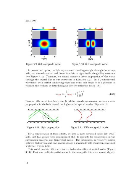
and 3.10).<br />
Figure 3.9: 0-0 waveguide mode Figure 3.10: 0-1 waveguide mode<br />
In geometrical optics, the light rays are not travelling straight through the waveguide,<br />
but are reflected up and down from left to right inside the guiding structure<br />
(see Figure 3.11). Therefore, we cannot assume a linear propagation of the waves<br />
through the crystal like in our derivation in Equation 3.23. In a 2-dimensional<br />
waveguide, with perfect conducting edges and width and height b, it is possible to<br />
consider these effects by introducing an effective refractive index [19].<br />
neff ≈<br />
�<br />
nbulk − 2<br />
� �2 λ<br />
2b<br />
(3.32)<br />
However, this model is rather crude. It neither considers evanescent waves nor wave<br />
propagation in the bulk crystal nor higher order spatial modes (Figure 3.12).<br />
Figure 3.11: Light propagation Figure 3.12: Different spatial modes<br />
For a consideration of these effects, we have a more advanced model [19] available,<br />
that has already been implemented [20]. It accounts for evanescences in the<br />
surrounding material and transversal modes. The differences, in refractive indices<br />
between bulk crystal and slab waveguide and a waveguide with evanescences are not<br />
negligible (Figure 3.13).<br />
This model predicts different refractive indices for different spatial modes (Figure<br />
3.14). That way multiple spatial modes in the waveguide introduce several slightly<br />
14