SMALL DAMS PETITS BARRAGES
SMALL DAMS PETITS BARRAGES
SMALL DAMS PETITS BARRAGES
- TAGS
- dams
- petits
- barrages
- cbdb.org.br

Create successful ePaper yourself
Turn your PDF publications into a flip-book with our unique Google optimized e-Paper software.
y multiplying the 1 hour chart values by factor of 0.96. Adjustments are then made for overwater<br />
wind speeds by multiplying the map values by the velocity ratios listed on Table 5.3.<br />
Table 5.3 – Wind Velocity Relationship – Water to Land (USBR, 1992)<br />
Effective Fetch (Fe) Wind Velocity Ratio<br />
(km)<br />
(over water/over land)<br />
0,8 1.08<br />
1,6 1.13<br />
3,2 1.21<br />
4,8 1.26<br />
6,4 1.28<br />
≥ 8 1.30<br />
The relationship between the wind velocity (Uf) over water and wind duration is found<br />
using charts based on the effective fetch (Fe).<br />
Compute the Design Wave<br />
Design wave terms are defined on Figure 5.3. Significant wave height (Hs) and wave<br />
period (T) are first computed from the design wind and effective fetch (steps 1 and 2), using<br />
design charts or equations. The deep water wave length (L) is then computed as follows:<br />
2<br />
L 5. 12T<br />
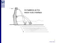
Wave run-up (R) is defined as the vertical height above still-water level (SWL) to which<br />
water from an incident wave will run up the face of the dam. Wave runup is calculated as<br />
follows:<br />
H<br />
R<br />
s<br />
0.<br />
5<br />
H s 0.<br />
4 cot<br />
L<br />
Correction factors are applied for run-up when the wave propagation direction is not<br />
normal to the upstream face of the dam. For embankment dams with smooth upstream faces,<br />
the computed run-up is increased by a factor of 1.5.<br />
Different design charts are used to evaluate run-up on rockfill dams or on earthen dams<br />
with a rock U/S protection.<br />
S<br />
SWL<br />
D<br />
Fig. 5.3 – Definition of Terms for Design Wave Parameters<br />
Wind setup (S) is computed as follows:<br />
L<br />
Ѳ<br />
R<br />
56