NOTICE TECHNIQUE PRODUIT et de MISE EN OEUVRE ... - DEF
NOTICE TECHNIQUE PRODUIT et de MISE EN OEUVRE ... - DEF
NOTICE TECHNIQUE PRODUIT et de MISE EN OEUVRE ... - DEF

Create successful ePaper yourself
Turn your PDF publications into a flip-book with our unique Google optimized e-Paper software.
Gamme ECS Cassiopée FORTE<br />
Notice technique produit <strong>et</strong> <strong>de</strong> mise en œuvre<br />
Document : 02.NTP.1241<br />
Indice : J<br />
Date : 08/06/12<br />
Page : 37/55<br />
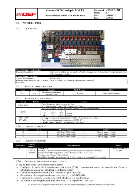
I.7 MODULE C20R<br />
I.7.1<br />
DESCRIPTION<br />
J2<br />
J3<br />
L1<br />
J1<br />
ST1 à ST20<br />
SW1 à SW20<br />
SW21<br />
B1<br />
Caractéristiques fonctionnelles<br />
Fonction(s) assurée(s)<br />
C<strong>et</strong>te carte i<strong>de</strong>ntifiée par un numéro d’esclave (codage) m<strong>et</strong> à disposition 20 relais paramétrables<br />
(téléchargement <strong>et</strong> cavalier).<br />
Caractéristiques électriques :<br />
Tension d’alimentation <strong>de</strong> 21V à 30V.<br />
Consommation maximale sur la source 10mA en condition <strong>de</strong> veille <strong>et</strong> 8.5mA par relais commandé.<br />
secondaire<br />
I.7.2<br />
I.7.3<br />
SIGNALISATIONS LUMINEUSES<br />
Voyant Couleur Fonction Mo<strong>de</strong> Normal Défaut<br />
L1 Vert<br />
Témoin du dialogue entre<br />
MB2B <strong>et</strong> C20R<br />
clignotant<br />
éteint : pas <strong>de</strong> dialogue<br />
SWITCHES DE CONFIGURATION<br />
Switch Libellé Fonction<br />
SW1 à SW20 -<br />
Choix du mo<strong>de</strong> <strong>de</strong> fonctionnement du relais :<br />
ON = Normalement Fermé ; OFF = Normalement Ouvert<br />
SW21 -<br />
N° 1 à 3 : configure l’adresse du module. Adresses 1 <strong>et</strong> 2 seulement possibles.<br />
1 2 3<br />
ON OFF OFF Adresse 1<br />
OFF ON OFF Adresse 2<br />
ST1 à ST20 - Si strapp ouvert, introduit une résistance 560 Ω ¼ W en série avec le contact<br />
PT3 à PT4 - Choix du protocole <strong>de</strong> communication avec MB2B SPI :<br />
Cavalier entre PT4 <strong>et</strong> PT5 : protocole avec "slave select"<br />
I.7.4<br />
LIAISONS INTERIEURES<br />
Connecteurs Nom Matériel connecté Support<br />
J1 - MB2B ou C20R suivante Câble en nappe 14 points<br />
J2 - MB2B ou C20R suivante Câble en nappe 14 points<br />
J3 - MB2B ou C20R suivante Câble en nappe 14 points<br />
I.7.5<br />
Connecteurs<br />
B1<br />
LIAISONS EXTERIEURES<br />
Matériel<br />
connecté<br />
selon FTR<br />
A3423R,<br />
A4408R<br />
Caractéristiques<br />
Nombre : 20<br />
Fonction : Délivrer <strong>de</strong>s contacts libres <strong>de</strong> potentiels selon <strong>de</strong>s événements déterminés.<br />
Nature : Sortie libre <strong>de</strong> potentiel, pouvoir <strong>de</strong> coupure 24W, Imax = 1 Adc<br />
Choix du contact RL ou LT par switches<br />
Possibilité d’introduire une résistance 560 Ω ¼ W en série avec le contact à l’ai<strong>de</strong> <strong>de</strong> strapp<br />
Ce document est la propriété exclusive <strong>de</strong> <strong>DEF</strong>, il ne doit être ni communiqué, ni reproduit sans l'accord écrit <strong>de</strong> <strong>DEF</strong>.<br />
Support<br />
2 fils <strong>de</strong> section 0,5 à<br />
2,5 mm²<br />
I.7.6 OPERATIONS NECESSAIRES A L’INSTALLATION<br />
Si une ou <strong>de</strong>ux cartes C20R optionnelles existent :<br />
‣ Configurer le mo<strong>de</strong> <strong>de</strong> fonctionnement <strong>de</strong>s cartes (C20R : normalement ouvert ou normalement fermé <strong>et</strong><br />
introduction ou non d’une résistance série dans le contact)<br />
‣ Configurer la première carte C20R à l’adresse n°1 puis l’installer.<br />
‣ Raccor<strong>de</strong>r le câble nappé fourni entre c<strong>et</strong>te carte (J1) <strong>et</strong> la MB2B (J9).<br />
‣ Configurer l’éventuelle secon<strong>de</strong> carte C20R à l’adresse n°2 puis l’installer.<br />
‣ Raccor<strong>de</strong>r le câble nappé fourni entre c<strong>et</strong>te carte (J1) <strong>et</strong> la première C20R (J2).