MANUALE ISTRUZIONI E CATALOGO RICAMBI ... - Nice-service.com
MANUALE ISTRUZIONI E CATALOGO RICAMBI ... - Nice-service.com
MANUALE ISTRUZIONI E CATALOGO RICAMBI ... - Nice-service.com

You also want an ePaper? Increase the reach of your titles
YUMPU automatically turns print PDFs into web optimized ePapers that Google loves.
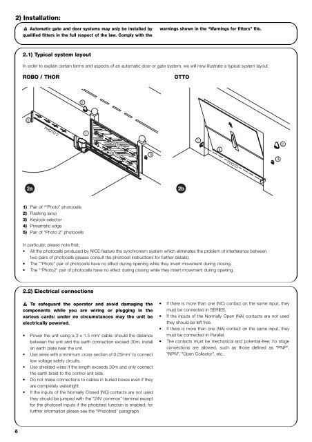
PHOTO2) Installation:! Automatic gate and door systems may only be installed byqualified fitters in the full respect of the law. Comply with thewarnings shown in the “Warnings for fitters” file.2.1) Typical system layoutIn order to explain certain terms and aspects of an automatic door or gate system, we will now illustrate a typical system layout.ROBO / THOROTTO25PHOTO 21PHOTOPHOTO314322a2b1) Pair of ““Photo” photocells2) Flashing lamp3) Keylock selector4) Pneumatic edge5) Pair of “Photo 2” photocellsIn particular, please note that:• All the photocells produced by NICE feature the synchronism system which eliminates the problem of interference betweentwo pairs of photocells (please consult the photocell instructions for further details).• The ““Photo” pair of photocells have no effect during opening while they invert movement during closing.• The ““Photo2” pair of photocells have no effect during closing while they invert movement during opening.2.2) Electrical connections! To safeguard the operator and avoid damaging the<strong>com</strong>ponents while you are wiring or plugging in thevarious cards: under no circumstances may the unit beelectrically powered.• Power the unit using a 3 x 1.5 mm 2 cable: should the distancebetween the unit and the earth connection exceed 30m, installan earth plate near the unit.• Use wires with a minimum cross-section of 0.25mm 2 to connectlow voltage safety circuits.• Use shielded wires if the length exceeds 30m and only connectthe earth braid to the control unit side.• Do not make connections to cables in buried boxes even if theyare <strong>com</strong>pletely watertight.• If the inputs of the Normally Closed (NC) contacts are not usedthey should be jumped with the “24V <strong>com</strong>mon” terminal exceptfor the photocell inputs if the phototest function is enabled, forfurther information please see the “Phototest” paragraph.• If there is more than one (NC) contact on the same input, theymust be connected in SERIES.• If the inputs of the Normally Open (NA) contacts are not usedthey should be left free.• If there is more than one (NA) contact on the same input, theymust be connected in Parallel.• The contacts must be mechanical and potential-free; no stageconnections are allowed, such as those defined as "PNP","NPN", "Open Collector", etc..6