MANUALE ISTRUZIONI E CATALOGO RICAMBI ... - Nice-service.com
MANUALE ISTRUZIONI E CATALOGO RICAMBI ... - Nice-service.com
MANUALE ISTRUZIONI E CATALOGO RICAMBI ... - Nice-service.com

Create successful ePaper yourself
Turn your PDF publications into a flip-book with our unique Google optimized e-Paper software.
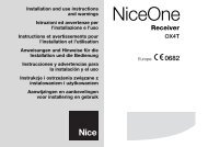
Switch 9: On = BrakeAt the end of the movement a motor brake procedure is performed, initially slight and then more incisive in order to stop the gate rapidly butwithout jolts.GBSwitch 10:OnROBO - THORWithout the PIU board fitted:• Gate open indicator with proportional flashingWith the PIU board fitted:• “Phototest”OTTOWithout the PIU board fitted:• Courtesy light time = 4 minutesWith the PIU board fitted:• “Phototest”This function controls photocell efficiency at the beginning of each manoeuvre. See the “Phototest” chapter.7) Using 2 control units on opposed leafsTo create an automation system working with 2 opposed leafs:• Use two motors with the control units connected as indicated infig. 5.• Connect the flashing light and the “Gate Open Indicator” to anyone of the two control units .• The inputs must be connected in parallel.• The “Common” of the inputs can be connected to one of the 2control units.• Connect the 0Volts (Terminal 5) of the two control units.• The “Phototest” function must not be used• The “Condominium” function ( Dip-Switch 3) should be fitted asthis allows the leafs to be resynchronised if the 2 control unitsbe<strong>com</strong>e unsynchronised.4443424113121110987654321200mA24 VCOMSCAFCAFCCPHOTOSTEP-BY-STEPOPENCLOSEFCAFCCPHOTOSTEP-BY-STEPOPENCLOSE4443424113121110987654321POWERINPUTFLASHING LIGHT200mA24 VCOMSCASTOPPHOTOSTEP-BY-STEPOPENCLOSEPOWERINPUTFLASHINGLIGHT513