W - Stahlwerk Thüringen
W - Stahlwerk Thüringen
W - Stahlwerk Thüringen

You also want an ePaper? Increase the reach of your titles
YUMPU automatically turns print PDFs into web optimized ePapers that Google loves.
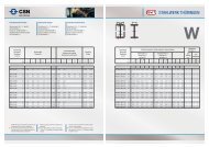
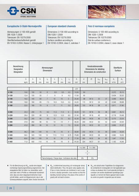
Europäische UStahlNormalprofile<br />
Abmessungen: U 100-400 gemäß<br />
DIN 1026-1:2009<br />
Toleranzen: EN 10279:2000<br />
Oberflächenbeschaffenheit gemäß<br />
EN 10163-3:2004, Klasse C, Untergruppe 1<br />
♦ Für die Berechnung von W pl.y wurde eine doppelrechteckige<br />
Spannungsverteilung angenommen. Der<br />
angegebene Wert ist daher nur anwendbar, wenn<br />
zwei oder mehr U-Profile so miteinander kombiniert<br />
sind, dass sie einen doppelsymmetrischen Querschnitt<br />
bilden, womit ein Biegemoment, das in der<br />
Schwerpunktebene angreift, keine Torsion hervorruft.<br />
28<br />
Bezeichnung<br />
Designation<br />
Désignation<br />
European standard channels<br />
Dimensions: U 100-400 according to<br />
DIN 1026-1:2009<br />
Tolerances: EN 10279:2000<br />
Surface condition according to<br />
EN 10163-3:2004, class C, subclass 1<br />
Abmessungen<br />
Dimensions<br />
♦ W pl.y is determined assuming a bi-rectangular stress<br />
block distribution. Thus, the given value applies only<br />
if two or more channels are combined in such a way<br />
to form a doubly symmetric cross-section so that the<br />
bending moment acting in the plane of the centre of<br />
gravity will not lead to torsion.<br />
Fers U normaux européens<br />
Dimensions: U 100-400 according to<br />
DIN 1026-1:2009<br />
Tolérances: EN 10279:2000<br />
Etat de surface conforme à<br />
EN 10163-3:2004, classe C, sous-classe 1<br />
Konstruktionsmaße<br />
Dimensions for detailing<br />
Dimensions de construction<br />
Oberfläche<br />
Surface<br />
G h b tw tf r1 r2 A d Ø emin emax AL AG kg/m mm mm mm mm mm mm mm2 mm mm mm m2 /m m2 /t<br />
U 100 10,6 100 50 6 8,5 8,5 4,5 13,50 64 - - - 0,372 35,10<br />
U 120 13,4 120 55 7 9 9 4,5 17,00 82 - - - 0,434 32,52<br />
U 140 16,0 140 60 7 10 10 5 20,40 98 M 12 33 37 0,489 30,54<br />
U 160 18,8 160 65 7,5 10,5 10,5 5,5 24,00 115 M 12 34 42 0,546 28,98<br />
U 180 22,0 180 70 8 11 11 5,5 28,00 133 M 16 38 41 0,611 27,80<br />
U 200 25,3 200 75 8,5 11,5 11,5 6 32,20 151 M 16 39 46 0,661 26,15<br />
U 220 29,4 220 80 9 12,5 12,5 6,5 37,40 167 M 16 40 51 0,718 24,46<br />
U 240 33,2 240 85 9,5 13 13 6,5 42,30 184 M 20 46 50 0,775 23,34<br />
U 260 37,9 260 90 10 14 14 7 48,30 200 M 22 50 52 0,834 22,00<br />
U 280 41,8 280 95 10 15 15 7,5 53,30 216 M 22 52 57 0,890 21,27<br />
U 300 46,2 300 100 10 16 16 8 58,80 232 M 24 55 59 0,950 20,58<br />
U 320 59,5 320 100 14 17,5 17,5 8,75 75,80 246 M 22 58 62 0,982 16,50<br />
U 350 60,6 350 100 14 16 16 8 77,30 282 M 22 56 62 1,047 17,25<br />
U 400 71,8 400 110 14 18 18 9 91,50 324 M 27 61 62 1,182 16,46<br />
u<br />
x10 2<br />
h ≤ 300 h > 300<br />
b<br />
_____<br />
2<br />
Flanschneigung | Flange slope | Inclinaison des ailes 8% 5%<br />
♦ W pl.y est calculé selon l’hypothèse d’un diagramme<br />
de contraintes bi-rectangulaire et n’est applicable que<br />
si deux ou plusieurs fers U sont associés de façon à<br />
constiuer une section doublement symétrique pour<br />
laquelle un moment de flexion agissant dans le plan<br />
du centre de gravité n’engendre pas de torsion.