Oleodinamica/Pneumatica Hydraulic/ Pneumatic
Oleodinamica/Pneumatica Hydraulic/ Pneumatic
Oleodinamica/Pneumatica Hydraulic/ Pneumatic

You also want an ePaper? Increase the reach of your titles
YUMPU automatically turns print PDFs into web optimized ePapers that Google loves.
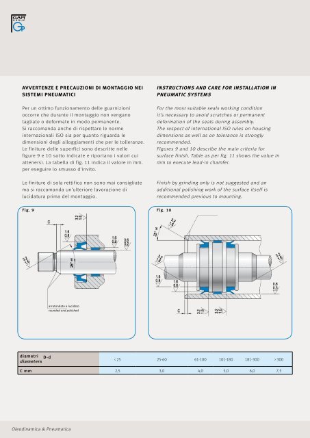
AVVERTEnZE E PRECAuZIOnI DI MOnTAGGIO nEI<br />
SISTEMI PnEuMATICI<br />
Per un ottimo funzionamento delle guarnizioni<br />
occorre che durante il montaggio non vengano<br />
tagliate o deformate in modo permanente.<br />
Si raccomanda anche di rispettare le norme<br />
internazionali ISO sia per quanto riguarda le<br />
dimensioni degli alloggiamenti che per le tolleranze.<br />
Le finiture delle superfici sono descritte nelle<br />
figure 9 e 10 sotto indicate e riportano i valori cui<br />
attenersi. La tabella di fig. 11 indica il valore in mm.<br />
per eseguire lo smusso d’invito.<br />
Le finiture di sola rettifica non sono mai consigliate<br />
ma si raccomanda un’ulteriore lavorazione di<br />
lucidatura prima del montaggio.<br />
Fig. 9<br />
diametri<br />
diameters D-d<br />
arrotondato e lucidato<br />
rounded and polished<br />
<strong>Oleodinamica</strong> & <strong><strong>Pneumatic</strong>a</strong><br />
InSTRuCTIOnS AnD CARE FOR InSTALLATIOn In<br />
PnEuMATIC SySTEMS<br />
For the most suitable seals working condition<br />
it’s necessary to avoid scratches or permanent<br />
deformation of the seals during assembly.<br />
The respect of international ISO rules on housing<br />
dimensions as well as on tolerance is strongly<br />
recommended.<br />
Figures 9 and 10 describe the main criteria for<br />
surface finish. Table as per fig. 11 shows the value in<br />
mm to execute lead-in chamfer.<br />
Finish by grinding only is not suggested and an<br />
additional polishing work of the surface itself is<br />
recommended previous to mounting.<br />
Fig. 10<br />
< 25 25-60 61-100 101-180 181-300 > 300<br />
C mm 2,5 3,0 4,0 5,0 6,0 7,5