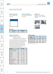
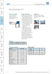
WSG RASCHIATORE COn STEP TIPO WSG Descrizione Il raschiatore tipo WSG ha la funzione di pulire lo stelo al suo rientro, mantenendo all’esterno le impurità. E’ composto da un’anima metallica incollata ad un elemento in poliuretano. La cava risulta aperta facilitando l’esecuzione della sede. Dati tecnici Velocità: < 0,8 m/s Temperatura: da – 35° C a + 100 ° C con punte fino a 110° C. Fluidi: agenti atmosferici, acqua a temperatura inferiore a 60° C, oli a base minerale (vedi TABELLA I pagg. 10-11) Materiale Il materiale del raschiatore è un poliuretano di durezza 93 Shore A e anima in acciaio. Codice materiale: CA Montaggio Il montaggio avviene in cava aperta. Togliere gli spigoli vivi e le bave per facilitarne l’inserimento. Attenzione: la cava dove alloggia il raschiatore deve essere in tolleranza di lavorazione come indicato nella colonna D. Il mancato rispetto della misura della tolleranza può causare la fuoriuscita del manufatto durante il movimento. <strong>Oleodinamica</strong> & <strong><strong>Pneumatic</strong>a</strong> WIPER WITH STEP TyPE WSG Description The function of the WSG wiper is to clean the rod while returning to position, blocking any external impurities. It is made up of a metal core glued to a polyurethane element. The groove is open and facilitates the design of the seat. Technical data Speed: < 0.8 m/s Temperature: from – 35° C to + 100 ° C with peaks till 110° C. Fluids: atmospheric factors, water at a temperature below 60° C, mineral oils (see TABLE I pages 10-11) Material The material of the wiper is a polyurethane with a hardness of 93 Shore A and steel core. Compound reference: CA Assembly The assembly is done in open groove. Remove any flash and cu ting edges to ease the insertion of the wiper. Warning: The housing of the wiper must be within the machining tolerance as shown in column D. The non observance of the tolerance measures can trigger the extrusion of the product during operations.
WSG disegno /drawing WSG dh9 DH10 Toll. E+0,2 C ART / ITEM 20,0 30,0 -0 4,0 0,8 WSG 0200 0300 040 CA 20,0 30,0 +0,033 5,0 1,0 WSG 0200 0300 050 CA * 20,0 30,0 7,0 1,5 WSG 0200 0300 070 CA 22,0 30,0 -0 4,0 0,8 WSG 0220 0300 040 CA 22,0 32,0 +0,039 5,0 1,0 WSG 0220 0320 050 CA * 22,0 32,0 7,0 1,5 WSG 0220 0320 070 CA 25,0 35,0 -0 5,0 1,5 WSG 0250 0350 050 CA * 25,0 35,0 +0,039 7,0 1,5 WSG 0250 0350 070 CA 28,0 38,0 5,0 1,0 WSG 0280 0350 050 CA 28,0 38,0 -0 7,0 1,5 WSG 0280 0380 070 CA 30,0 40,0 +0,039 5,0 1,0 WSG 0300 0400 050 CA 30,0 40,0 7,0 1,5 WSG 0300 0400 070 CA 32,0 42,0 -0 5,0 1,0 WSG 0320 0420 050 CA 32,0 42,0 +0,039 7,0 1,5 WSG 0320 0420 070 CA 35,0 45,0 5,0 1,0 WSG 0350 0450 050 CA * 35,0 45,0 -0 7,0 1,5 WSG 0350 0450 070 CA 36,0 46,0 +0,039 5,0 1,0 WSG 0360 0460 050 CA 38,0 48,0 7,0 1,0 WSG 0380 0480 070 CA 40,0 50,0 -0 5,0 1,0 WSG 0400 0500 050 CA * 40,0 50,0 +0,046 7,0 1,5 WSG 0400 0500 070 CA 42,0 52,0 7,0 1,5 WSG 0420 0520 070 CA arrotondato e lucidato rounded and polished dh9 DH10 Toll. E+0,2 C ART / ITEM 45,0 55,0 -0 7,0 1,5 WSG 0450 0550 070 CA 50,0 60,0 +0,046 5,0 1,0 WSG 0500 0600 050 CA * 50,0 60,0 7,0 1,5 WSG 0500 0600 070 CA 55,0 65,0 -0 7,0 1,5 WSG 0550 0650 070 CA * 56,0 66,0 +0,046 7,0 1,5 WSG 0560 0660 070 CA 60,0 70,0 5,0 1,0 WSG 0600 0700 050 CA 60,0 70,0 -0 7,0 1,5 WSG 0600 0700 070 CA 65,0 75,0 0,046 7,0 1,5 WSG 0650 0750 070 CA * 70,0 80,0 7,0 1,5 WSG 0700 0800 070 CA 75,0 85,0 -0 7,0 1,5 WSG 0750 0850 070 CA * 80,0 90,0 +0,054 7,0 1,5 WSG 0800 0900 070 CA 85,0 95,0 7,0 1,5 WSG 0850 0950 070 CA * 90,0 100,0 -0 7,0 1,5 WSG 0900 1000 070 CA 95,0 105,0 +0,054 7,0 1,5 WSG 0950 1050 070 CA 100,0 110,0 7,0 1,5 WSG 1000 1100 070 CA 110,0 120,0 -0 7,0 1,5 WSG 1100 1200 070 CA 120,0 130,0 +0,063 7,0 1,5 WSG 1200 1300 070 CA * in conformità alle norme ISO 3320 – in accordance with norms ISO 3320 <strong>Hydraulic</strong>/ <strong>Pneumatic</strong> 95 Sistemi di tenuta per oleodinamica <strong>Hydraulic</strong> sealing systems
- Page 1 and 2:
O l e o d i n a m i c a / P n e u m
- Page 3 and 4:
Indice Contents Sezione tecnica 5 S
- Page 5 and 6:
Sezione tecnica generale Technical
- Page 7 and 8:
del materiale con cui è realizzata
- Page 9 and 10:
con le guarnizioni di tenuta. Sono
- Page 11 and 12:
Tab. 1 - Resistenza chimica dei mat
- Page 13 and 14:
superficie di contatto con evidente
- Page 15 and 16:
dimensioni nominali nominal dimensi
- Page 17 and 18:
Sistemi di tenuta per oleodinamica
- Page 19 and 20:
schema cilindro idraulico B hydraul
- Page 21 and 22:
Profilo Profile Profilo Profile Pro
- Page 23 and 24:
Profilo Profile RASCHIATORI PER EST
- Page 25 and 26:
Guarnizioni stelo Nei cilindri oleo
- Page 27 and 28:
RSA disegno /drawing RSA dh9 DH10 h
- Page 29 and 30:
RSA dh9 DH10 h E+0,2 C ART / ITEM 6
- Page 31 and 32:
RSB disegno /drawing RSB dh9 DH10 h
- Page 33 and 34:
RSB dh9 DH10 h E+0,2 C ART / ITEM 8
- Page 35 and 36:
Hydraulic/ Pneumatic 35 Sistemi di
- Page 37 and 38:
disegno /drawing RSC dh9 DH10 h E+0
- Page 39 and 40:
RSC dh9 DH10 h E+0,2 C ART / ITEM 7
- Page 41 and 42:
RSD disegno /drawing RSD dh9 DH10 h
- Page 43 and 44: RSD dh9 DH10 h E+0,2 C ART / ITEM 1
- Page 45 and 46: RSO disegno / drawing RSO dh9 DH10
- Page 47 and 48: Hydraulic/ Pneumatic 47 Sistemi di
- Page 49 and 50: RBR disegno / drawing RBR dh9 DH10
- Page 51 and 52: RPS disegno / drawing RPS dh11 d1h9
- Page 53 and 54: dh11 d1h9 RPS DH9 D1H10 h E+0,2 d2*
- Page 55 and 56: Hydraulic/ Pneumatic 55 Sistemi di
- Page 57 and 58: Fig. 4 Fig. 5 Fig. 6 Due guarnizion
- Page 59 and 60: PSA disegno / drawing PSA DH9 dh9 h
- Page 61 and 62: Hydraulic/ Pneumatic 61 Sistemi di
- Page 63 and 64: PAE disegno / drawing PAE DH9 dh9 d
- Page 65 and 66: PSH+RR disegno /drawing PSH + RR DH
- Page 67 and 68: PSO disegno / drawing PSO DH9 dh9 E
- Page 69 and 70: Hydraulic/ Pneumatic 69 Sistemi di
- Page 71 and 72: PSQ disegno /drawing PSQ DH9 dh9 E+
- Page 73 and 74: KDSA disegno /drawing KDSA DH9 dh9
- Page 75 and 76: KDSB DH9 dh9 E+0,2 d1h9 d2±0,2 E1
- Page 77 and 78: KDSP disegno /drawing KDSP DH9 dh9
- Page 79 and 80: KDAE disegno /drawing KDAE DH9 dh9
- Page 81 and 82: HIS disegno /drawing HIS diametri d
- Page 83 and 84: HIS dh9 D -0 +0,05 E +0,2 C ART / I
- Page 85 and 86: HES disegno /drawing HES diametri d
- Page 87 and 88: D H9 HES d + 0 0,05 E +0,2 C ART /
- Page 89 and 90: Hydraulic/ Pneumatic 89 Sistemi di
- Page 91 and 92: WSL disegno /drawing WSL dh9 DH10 E
- Page 93: Hydraulic/ Pneumatic 93 Sistemi di
- Page 97 and 98: WWS disegno /drawing WWS dh9 DH10 E
- Page 99 and 100: WAT disegno /drawing WAT dh9 DH10 D
- Page 101 and 102: WED disegno /drawing WED dh9 DH10 E
- Page 103 and 104: Hydraulic/ Pneumatic 103 Sistemi di
- Page 105 and 106: WEL disegno /drawing WEL DH9 dh9 E
- Page 107 and 108: Tenute statiche Static seals Hydrau
- Page 109 and 110: O-RING / O-RING Condizioni massime
- Page 111 and 112: SSA disegno /drawing SSA arrotondat
- Page 113 and 114: SSA DH10 dh9 E+0,2 R d1h9 D1H10 ART
- Page 115 and 116: FSA disegno /drawing FSA INCH DIM.
- Page 117 and 118: VRA disegno /drawing VRA D d h E+0,
- Page 119 and 120: O-RING Materiale Esistono, come ind
- Page 121 and 122: OR disegno /drawing OR S sezione se
- Page 123 and 124: OR d toll ± o-ring altro rif. alte
- Page 125 and 126: OR d toll ± o-ring altro rif. alte
- Page 127 and 128: OR d toll ± o-ring altro rif. alte
- Page 129 and 130: OR d toll ± o-ring altro rif. alte
- Page 131 and 132: OR d toll ± o-ring altro rif. alte
- Page 133 and 134: Sistemi di tenuta per pneumatica Pn
- Page 135 and 136: schema cilindro pneumatico B / pneu
- Page 137 and 138: Profilo Profile Profilo Profile ANE
- Page 139 and 140: Hydraulic/ Pneumatic 139 Sistemi di
- Page 141 and 142: RSP disegno /drawing RSP arrotondat
- Page 143 and 144: Hydraulic/ Pneumatic 143 Sistemi di
- Page 145 and 146:
SRS disegno /drawing SRS arrotondat
- Page 147 and 148:
CSA disegno /drawing CSA dh10 toll
- Page 149 and 150:
PSP disegno /drawing PSP DH11 dh10
- Page 151 and 152:
Hydraulic/ Pneumatic 151 Sistemi di
- Page 153 and 154:
MPS disegno /drawing MPS arrotondat
- Page 155 and 156:
MPS disegno /drawing MPS arrotondat
- Page 157 and 158:
SPS disegno /drawing SPS DH11 dh10
- Page 159 and 160:
ISA disegno /drawing ISA diametri d
- Page 161 and 162:
ESA disegno /drawing ESA diametri d
- Page 163 and 164:
Hydraulic/ Pneumatic 163 Sistemi di
- Page 165 and 166:
LWA disegno /drawing LWA arrotondat
- Page 167 and 168:
BWA disegno /drawing BWA df9 DH10 T
- Page 169 and 170:
Hydraulic/ Pneumatic 169 Sistemi di
- Page 171 and 172:
BWS disegno /drawing BWS arrotondat
- Page 173 and 174:
BWS disegno /drawing BWS arrotondat
- Page 175:
BWH disegno /drawing BWH arrotondat