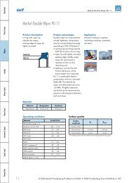
ESA FASCE DI GuIDA PER PISTOnE TIPO ESA Descrizione Per evitare il contatto diretto tra lo stelo e la testata del cilindro, e tra il pistone e la camicia, che nella maggior parte dei cilindri pneumatici è di alluminio, si inserisce una fascia di guida tipo ESA che serve per tenere guidato tutto il sistema. Le fasce di guida sono stampate con un materiale auto lubrificante, non abrasivo, studiato appositamente per favorire uno scorrimento lineare. Il profilo della guida presenta smussi sia all’interno sia all’esterno che facilitano il montaggio dello stelo e del pistone. Limiti d’impiego Velocità: < 1 m/s Temperatura: da - 40° C a + 115° C Carico statico: fino a 36 N/mm 2 Materiale Poliacetalica modificata. Grazie all’aggiunta di particolari additivi si è realizzato un materiale molto scorrevole e non abrasivo. Codice materiale standard: R3 Vantaggi – Ottimo rapporto prezzo/prestazioni – Basso effetto stick-slip − Buona resistenza alla compressione <strong>Oleodinamica</strong> & <strong><strong>Pneumatic</strong>a</strong> PISTOn SLyDRInGS TyPE ESA Description Given that most pneumatic cylinders are made of aluminium, a wear ring ESA is inserted between the piston and the bore in order to prevent the direct contact between the rod and the cylinder’s head. The function of the friction ring is to guide all the packing. The wear rings are moulded in non-abrasive autolubricating material, which has been purpose designed to support linear sliding. The wear ring profile has chamfers both inside and outside to facilitate the installation of the rod and the piston. Technical data Speed: < 1 m/s Temperature: from - 40° C up to + 115° C Static Strength: up to 36 N/mm 2 Material Polyacetalic resin. Through the use of additional compounds a very slick, anti-friction material has been developed. Standard compound reference: R3 Advantages – Excellent price/performance ratio – Low stick-slip effect − Good compressive strength
ESA disegno /drawing ESA diametri diameters D-d DH11 dh7 toll h7 E+0,2 S-0,08 ART / ITEM 8,0 4,9 0/-0.012 2,5 1,55 ESA 0080 0049 025 R3 10,0 6,9 0/-0.015 2,5 1,55 ESA 0100 0069 025 R3 10,0 6,9 0/-0.015 4,0 1,55 ESA 0100 0069 040 R3 12,0 8,9 0/-0.015 4,0 1,55 ESA 0120 0089 040 R3 14,0 10,9 0/-0.018 4,0 1,55 ESA 0140 0109 040 R3 15,0 11,9 0/-0.018 4,0 1,55 ESA 0150 0119 040 R3 16,0 12,9 0/-0.018 4,0 1,55 ESA 0160 0129 040 R3 16,0 12,0 0/-0.018 9,7 2,00 ESA 0160 0120 097 R3 18,0 14,9 0/-0.018 4,0 1,55 ESA 0180 0149 040 R3 20,0 16,0 0/-0.018 8,2 2,00 ESA 0200 0160 082 R3 20,0 16,0 0/-0.018 9,7 2,00 ESA 0200 0160 097 R3 20,0 16,9 0/-0.018 4,0 1,55 ESA 0200 0169 040 R3 21,0 17,0 0/-0.018 8,2 2,00 ESA 0210 0170 082 R3 22,0 18,0 0/-0.018 9,7 2,00 ESA 0220 0180 097 R3 25,0 21,0 0/-0.021 8,2 2,00 ESA 0250 0210 082 R3 arrotondato e lucidato rounded and polished 0 - 50 51 - 100 101 - 150 151 - 300 z. mm ≥ 2,0 2,5 3,0 3,5 DH11 dh7 toll h7 E+0,2 S-0,08 ART / ITEM 25,0 21,9 0/-0.021 4,0 1,55 ESA 0250 0219 040 R3 26,0 22,0 0/-0.021 8,2 2,00 ESA 0260 0220 082 R3 30,0 25,8 0/-0.021 5,0 2,10 ESA 0300 0258 050 R3 30,0 26,0 0/-0.021 5,0 2,00 ESA 0300 0260 050 R3 30,0 26,0 0/-0.021 8,2 2,00 ESA 0300 0260 082 R3 32,0 26,1 0/-0.021 5,0 2,95 ESA 0320 0261 050 R3 32,0 28,0 0/-0.021 5,0 2,00 ESA 0320 0280 050 R3 32,0 28,0 0/-0.021 8,2 2,00 ESA 0320 0280 082 R3 32,0 28,9 0/-0.021 4,0 1,55 ESA 0320 0289 040 R3 35,0 31,0 0/-0.025 8,2 2,00 ESA 0350 0310 082 R3 40,0 36,0 0/-0.025 5,0 2,00 ESA 0400 0360 050 R3 40,0 36,0 0/-0.025 8,2 2,00 ESA 0400 0360 082 R3 40,0 37,0 0/-0.025 12,0 1,50 ESA 0400 0370 120 R3 45,0 41,0 0/-0.025 10,2 2,00 ESA 0450 0410 102 R3 50,0 46,0 0/-0.025 5,2 2,00 ESA 0500 0460 052 R3 <strong>Hydraulic</strong>/ <strong>Pneumatic</strong> 161 Sistemi di tenuta per pneumatica <strong>Pneumatic</strong> sealing systems
- Page 1 and 2:
O l e o d i n a m i c a / P n e u m
- Page 3 and 4:
Indice Contents Sezione tecnica 5 S
- Page 5 and 6:
Sezione tecnica generale Technical
- Page 7 and 8:
del materiale con cui è realizzata
- Page 9 and 10:
con le guarnizioni di tenuta. Sono
- Page 11 and 12:
Tab. 1 - Resistenza chimica dei mat
- Page 13 and 14:
superficie di contatto con evidente
- Page 15 and 16:
dimensioni nominali nominal dimensi
- Page 17 and 18:
Sistemi di tenuta per oleodinamica
- Page 19 and 20:
schema cilindro idraulico B hydraul
- Page 21 and 22:
Profilo Profile Profilo Profile Pro
- Page 23 and 24:
Profilo Profile RASCHIATORI PER EST
- Page 25 and 26:
Guarnizioni stelo Nei cilindri oleo
- Page 27 and 28:
RSA disegno /drawing RSA dh9 DH10 h
- Page 29 and 30:
RSA dh9 DH10 h E+0,2 C ART / ITEM 6
- Page 31 and 32:
RSB disegno /drawing RSB dh9 DH10 h
- Page 33 and 34:
RSB dh9 DH10 h E+0,2 C ART / ITEM 8
- Page 35 and 36:
Hydraulic/ Pneumatic 35 Sistemi di
- Page 37 and 38:
disegno /drawing RSC dh9 DH10 h E+0
- Page 39 and 40:
RSC dh9 DH10 h E+0,2 C ART / ITEM 7
- Page 41 and 42:
RSD disegno /drawing RSD dh9 DH10 h
- Page 43 and 44:
RSD dh9 DH10 h E+0,2 C ART / ITEM 1
- Page 45 and 46:
RSO disegno / drawing RSO dh9 DH10
- Page 47 and 48:
Hydraulic/ Pneumatic 47 Sistemi di
- Page 49 and 50:
RBR disegno / drawing RBR dh9 DH10
- Page 51 and 52:
RPS disegno / drawing RPS dh11 d1h9
- Page 53 and 54:
dh11 d1h9 RPS DH9 D1H10 h E+0,2 d2*
- Page 55 and 56:
Hydraulic/ Pneumatic 55 Sistemi di
- Page 57 and 58:
Fig. 4 Fig. 5 Fig. 6 Due guarnizion
- Page 59 and 60:
PSA disegno / drawing PSA DH9 dh9 h
- Page 61 and 62:
Hydraulic/ Pneumatic 61 Sistemi di
- Page 63 and 64:
PAE disegno / drawing PAE DH9 dh9 d
- Page 65 and 66:
PSH+RR disegno /drawing PSH + RR DH
- Page 67 and 68:
PSO disegno / drawing PSO DH9 dh9 E
- Page 69 and 70:
Hydraulic/ Pneumatic 69 Sistemi di
- Page 71 and 72:
PSQ disegno /drawing PSQ DH9 dh9 E+
- Page 73 and 74:
KDSA disegno /drawing KDSA DH9 dh9
- Page 75 and 76:
KDSB DH9 dh9 E+0,2 d1h9 d2±0,2 E1
- Page 77 and 78:
KDSP disegno /drawing KDSP DH9 dh9
- Page 79 and 80:
KDAE disegno /drawing KDAE DH9 dh9
- Page 81 and 82:
HIS disegno /drawing HIS diametri d
- Page 83 and 84:
HIS dh9 D -0 +0,05 E +0,2 C ART / I
- Page 85 and 86:
HES disegno /drawing HES diametri d
- Page 87 and 88:
D H9 HES d + 0 0,05 E +0,2 C ART /
- Page 89 and 90:
Hydraulic/ Pneumatic 89 Sistemi di
- Page 91 and 92:
WSL disegno /drawing WSL dh9 DH10 E
- Page 93 and 94:
Hydraulic/ Pneumatic 93 Sistemi di
- Page 95 and 96:
WSG disegno /drawing WSG dh9 DH10 T
- Page 97 and 98:
WWS disegno /drawing WWS dh9 DH10 E
- Page 99 and 100:
WAT disegno /drawing WAT dh9 DH10 D
- Page 101 and 102:
WED disegno /drawing WED dh9 DH10 E
- Page 103 and 104:
Hydraulic/ Pneumatic 103 Sistemi di
- Page 105 and 106:
WEL disegno /drawing WEL DH9 dh9 E
- Page 107 and 108:
Tenute statiche Static seals Hydrau
- Page 109 and 110: O-RING / O-RING Condizioni massime
- Page 111 and 112: SSA disegno /drawing SSA arrotondat
- Page 113 and 114: SSA DH10 dh9 E+0,2 R d1h9 D1H10 ART
- Page 115 and 116: FSA disegno /drawing FSA INCH DIM.
- Page 117 and 118: VRA disegno /drawing VRA D d h E+0,
- Page 119 and 120: O-RING Materiale Esistono, come ind
- Page 121 and 122: OR disegno /drawing OR S sezione se
- Page 123 and 124: OR d toll ± o-ring altro rif. alte
- Page 125 and 126: OR d toll ± o-ring altro rif. alte
- Page 127 and 128: OR d toll ± o-ring altro rif. alte
- Page 129 and 130: OR d toll ± o-ring altro rif. alte
- Page 131 and 132: OR d toll ± o-ring altro rif. alte
- Page 133 and 134: Sistemi di tenuta per pneumatica Pn
- Page 135 and 136: schema cilindro pneumatico B / pneu
- Page 137 and 138: Profilo Profile Profilo Profile ANE
- Page 139 and 140: Hydraulic/ Pneumatic 139 Sistemi di
- Page 141 and 142: RSP disegno /drawing RSP arrotondat
- Page 143 and 144: Hydraulic/ Pneumatic 143 Sistemi di
- Page 145 and 146: SRS disegno /drawing SRS arrotondat
- Page 147 and 148: CSA disegno /drawing CSA dh10 toll
- Page 149 and 150: PSP disegno /drawing PSP DH11 dh10
- Page 151 and 152: Hydraulic/ Pneumatic 151 Sistemi di
- Page 153 and 154: MPS disegno /drawing MPS arrotondat
- Page 155 and 156: MPS disegno /drawing MPS arrotondat
- Page 157 and 158: SPS disegno /drawing SPS DH11 dh10
- Page 159: ISA disegno /drawing ISA diametri d
- Page 163 and 164: Hydraulic/ Pneumatic 163 Sistemi di
- Page 165 and 166: LWA disegno /drawing LWA arrotondat
- Page 167 and 168: BWA disegno /drawing BWA df9 DH10 T
- Page 169 and 170: Hydraulic/ Pneumatic 169 Sistemi di
- Page 171 and 172: BWS disegno /drawing BWS arrotondat
- Page 173 and 174: BWS disegno /drawing BWS arrotondat
- Page 175: BWH disegno /drawing BWH arrotondat