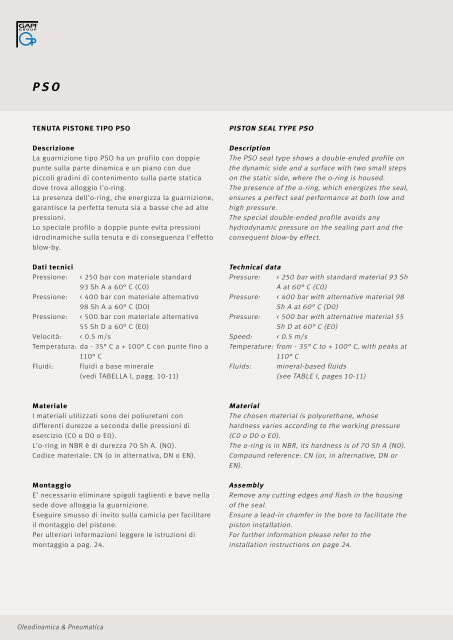
PSO TEnuTA PISTOnE TIPO PSO Descrizione La guarnizione tipo PSO ha un profilo con doppie punte sulla parte dinamica e un piano con due piccoli gradini di contenimento sulla parte statica dove trova alloggio l’o-ring. La presenza dell’o-ring, che energizza la guarnizione, garantisce la perfetta tenuta sia a basse che ad alte pressioni. Lo speciale profilo a doppie punte evita pressioni idrodinamiche sulla tenuta e di conseguenza l’effetto blow-by. Dati tecnici Pressione: < 250 bar con materiale standard 93 Sh A a 60° C (C0) Pressione: < 400 bar con materiale alternativo 98 Sh A a 60° C (D0) Pressione: < 500 bar con materiale alternativo 55 Sh D a 60° C (E0) Velocità: < 0.5 m/s Temperatura: da - 35° C a + 100° C con punte fino a 110° C Fluidi: fluidi a base minerale (vedi TABELLA I, pagg. 10-11) Materiale I materiali utilizzati sono dei poliuretani con differenti durezze a seconda delle pressioni di esercizio (C0 o D0 o E0). L’o-ring in NBR è di durezza 70 Sh A. (N0). Codice materiale: CN (o in alternativa, DN o EN). Montaggio E’ necessario eliminare spigoli taglienti e bave nella sede dove alloggia la guarnizione. Eseguire smusso di invito sulla camicia per facilitare il montaggio del pistone. Per ulteriori informazioni leggere le istruzioni di montaggio a pag. 24. <strong>Oleodinamica</strong> & <strong><strong>Pneumatic</strong>a</strong> PISTOn SEAL TyPE PSO Description The PSO seal type shows a double-ended profile on the dynamic side and a surface with two small steps on the static side, where the o-ring is housed. The presence of the o-ring, which energizes the seal, ensures a perfect seal performance at both low and high pressure. The special double-ended profile avoids any hydrodynamic pressure on the sealing part and the consequent blow-by e fect. Technical data Pressure: < 250 bar with standard material 93 Sh A at 60° C (C0) Pressure: < 400 bar with alternative material 98 Sh A at 60° C (D0) Pressure: < 500 bar with alternative material 55 Sh D at 60° C (E0) Speed: < 0.5 m/s Temperature: from - 35° C to + 100° C, with peaks at 110° C Fluids: mineral-based fluids (see TABLE I, pages 10-11) Material The chosen material is polyurethane, whose hardness varies according to the working pressure (C0 o D0 o E0). The o-ring is in NBR, its hardness is of 70 Sh A (N0). Compound reference: CN (or, in alternative, DN or EN). Assembly Remove any cutting edges and flash in the housing of the seal. Ensure a lead-in chamfer in the bore to facilitate the piston installation. For further information please refer to the installation instructions on page 24.
PSO disegno / drawing PSO DH9 dh9 E+0,2 C R o-ring (no) ART / ITEM 12,00 7,1 2,2 2,0 0,2 OR 016 PSO 0120 0710 022 CN * 20,00 12,50 3,2 3,0 0,2 OR 112 PSO 0200 0125 032 CN 22,00 14,50 3,2 3,0 0,2 OR 113 PSO 0220 0145 032 CN 24,00 16,50 3,2 3,0 0,2 OR 114 PSO 0240 0165 032 CN * 25,00 14,00 4,2 4,0 0,4 OR 207 PSO 0250 0140 042 CN * 25,00 17,50 3,2 3,0 0,2 OR 115 PSO 0250 0175 032 CN 28,00 20,50 3,2 3,0 0,4 OR 117 PSO 0280 0205 032 CN 30,00 22,50 3,2 3,0 0,4 OR 118 PSO 0300 0225 032 CN 32,00 21,00 4,2 4,0 0,4 OR 211 PSO 0320 0210 042 CN * 32,00 24,50 3,2 3,0 0,4 OR 119 PSO 0320 0245 032 CN 35,00 24,00 4,2 4,0 0,4 OR 213 PSO 0350 0240 042 CN 35,00 27,50 3,2 3,0 0,4 OR 121 PSO 0350 0275 032 CN 36,00 25,00 4,2 4,0 0,4 OR 213 PSO 0360 0250 042 CN 36,00 28,50 3,2 3,0 0,4 OR 122 PSO 0360 0285 032 CN 38,00 30,50 3,2 3,0 0,4 OR 123 PSO 0380 0305 032 CN 40,00 24,50 6,3 5,0 0,5 OR 318 PSO 0400 0245 063 CN * 40,00 29,00 4,2 4,0 0,4 OR 216 PSO 0400 0290 042 CN 42,00 31,00 4,2 4,0 0,5 OR 217 PSO 0420 0310 042 CN DH9 dh9 E+0,2 C R o-ring (no) ART / ITEM 45,00 29,50 6,3 5,0 0,5 OR 320 PSO 0450 0295 063 CN 45,00 34,00 4,2 4,0 0,5 OR 219 PSO 0450 0340 042 CN 48,00 37,00 4,2 4,0 0,5 OR 221 PSO 0480 0370 042 CN 49,00 38,00 4,2 4,0 0,5 OR 222 PSO 0490 0380 042 CN 50,00 34,50 6,3 5,0 0,5 OR 324 PSO 0500 0345 063 CN * 50,00 39,00 4,2 4,0 0,5 OR 222 PSO 0500 0390 042 CN 50,80 39,80 4,2 4,0 0,5 OR 222 PSO 0508 0398 042 CN 52,00 36,50 6,3 5,0 0,5 OR 324 PSO 0520 0365 063 CN 55,00 39,50 6,3 5,0 0,5 OR 325 PSO 0550 0395 063 CN 55,00 44,00 4,2 4,0 0,5 OR 224 PSO 0550 0440 042 CN 57,00 46,00 4,2 4,0 0,5 OR 224 PSO 0570 0460 042 CN 60,00 44,50 6,3 5,0 0,5 OR 327 PSO 0600 0445 063 CN 60,00 49,00 4,2 4,0 0,5 OR 225 PSO 0600 0490 042 CN * 63,00 47,50 6,3 5,0 0,5 OR 328 PSO 0630 0475 063 CN * 63,00 52,00 4,2 4,0 0,5 OR 226 PSO 0630 0520 042 CN 63,50 52,50 4,2 4,0 0,5 OR 226 PSO 0635 0525 042 CN 65,00 49,50 6,3 5,0 0,5 OR 328 PSO 0650 0495 063 CN 65,00 54,00 4,2 4,0 0,5 OR 227 PSO 0650 0540 042 CN * in conformità alle norme ISO/DIN 5597 e ISO 5597/1 – in accordance with norms ISO/DIN 5597 and ISO 5597/1 arrotondato e lucidato rounded and polished <strong>Hydraulic</strong>/ <strong>Pneumatic</strong> 67 Sistemi di tenuta per oleodinamica <strong>Hydraulic</strong> sealing systems
- Page 1 and 2:
O l e o d i n a m i c a / P n e u m
- Page 3 and 4:
Indice Contents Sezione tecnica 5 S
- Page 5 and 6:
Sezione tecnica generale Technical
- Page 7 and 8:
del materiale con cui è realizzata
- Page 9 and 10:
con le guarnizioni di tenuta. Sono
- Page 11 and 12:
Tab. 1 - Resistenza chimica dei mat
- Page 13 and 14:
superficie di contatto con evidente
- Page 15 and 16: dimensioni nominali nominal dimensi
- Page 17 and 18: Sistemi di tenuta per oleodinamica
- Page 19 and 20: schema cilindro idraulico B hydraul
- Page 21 and 22: Profilo Profile Profilo Profile Pro
- Page 23 and 24: Profilo Profile RASCHIATORI PER EST
- Page 25 and 26: Guarnizioni stelo Nei cilindri oleo
- Page 27 and 28: RSA disegno /drawing RSA dh9 DH10 h
- Page 29 and 30: RSA dh9 DH10 h E+0,2 C ART / ITEM 6
- Page 31 and 32: RSB disegno /drawing RSB dh9 DH10 h
- Page 33 and 34: RSB dh9 DH10 h E+0,2 C ART / ITEM 8
- Page 35 and 36: Hydraulic/ Pneumatic 35 Sistemi di
- Page 37 and 38: disegno /drawing RSC dh9 DH10 h E+0
- Page 39 and 40: RSC dh9 DH10 h E+0,2 C ART / ITEM 7
- Page 41 and 42: RSD disegno /drawing RSD dh9 DH10 h
- Page 43 and 44: RSD dh9 DH10 h E+0,2 C ART / ITEM 1
- Page 45 and 46: RSO disegno / drawing RSO dh9 DH10
- Page 47 and 48: Hydraulic/ Pneumatic 47 Sistemi di
- Page 49 and 50: RBR disegno / drawing RBR dh9 DH10
- Page 51 and 52: RPS disegno / drawing RPS dh11 d1h9
- Page 53 and 54: dh11 d1h9 RPS DH9 D1H10 h E+0,2 d2*
- Page 55 and 56: Hydraulic/ Pneumatic 55 Sistemi di
- Page 57 and 58: Fig. 4 Fig. 5 Fig. 6 Due guarnizion
- Page 59 and 60: PSA disegno / drawing PSA DH9 dh9 h
- Page 61 and 62: Hydraulic/ Pneumatic 61 Sistemi di
- Page 63 and 64: PAE disegno / drawing PAE DH9 dh9 d
- Page 65: PSH+RR disegno /drawing PSH + RR DH
- Page 69 and 70: Hydraulic/ Pneumatic 69 Sistemi di
- Page 71 and 72: PSQ disegno /drawing PSQ DH9 dh9 E+
- Page 73 and 74: KDSA disegno /drawing KDSA DH9 dh9
- Page 75 and 76: KDSB DH9 dh9 E+0,2 d1h9 d2±0,2 E1
- Page 77 and 78: KDSP disegno /drawing KDSP DH9 dh9
- Page 79 and 80: KDAE disegno /drawing KDAE DH9 dh9
- Page 81 and 82: HIS disegno /drawing HIS diametri d
- Page 83 and 84: HIS dh9 D -0 +0,05 E +0,2 C ART / I
- Page 85 and 86: HES disegno /drawing HES diametri d
- Page 87 and 88: D H9 HES d + 0 0,05 E +0,2 C ART /
- Page 89 and 90: Hydraulic/ Pneumatic 89 Sistemi di
- Page 91 and 92: WSL disegno /drawing WSL dh9 DH10 E
- Page 93 and 94: Hydraulic/ Pneumatic 93 Sistemi di
- Page 95 and 96: WSG disegno /drawing WSG dh9 DH10 T
- Page 97 and 98: WWS disegno /drawing WWS dh9 DH10 E
- Page 99 and 100: WAT disegno /drawing WAT dh9 DH10 D
- Page 101 and 102: WED disegno /drawing WED dh9 DH10 E
- Page 103 and 104: Hydraulic/ Pneumatic 103 Sistemi di
- Page 105 and 106: WEL disegno /drawing WEL DH9 dh9 E
- Page 107 and 108: Tenute statiche Static seals Hydrau
- Page 109 and 110: O-RING / O-RING Condizioni massime
- Page 111 and 112: SSA disegno /drawing SSA arrotondat
- Page 113 and 114: SSA DH10 dh9 E+0,2 R d1h9 D1H10 ART
- Page 115 and 116: FSA disegno /drawing FSA INCH DIM.
- Page 117 and 118:
VRA disegno /drawing VRA D d h E+0,
- Page 119 and 120:
O-RING Materiale Esistono, come ind
- Page 121 and 122:
OR disegno /drawing OR S sezione se
- Page 123 and 124:
OR d toll ± o-ring altro rif. alte
- Page 125 and 126:
OR d toll ± o-ring altro rif. alte
- Page 127 and 128:
OR d toll ± o-ring altro rif. alte
- Page 129 and 130:
OR d toll ± o-ring altro rif. alte
- Page 131 and 132:
OR d toll ± o-ring altro rif. alte
- Page 133 and 134:
Sistemi di tenuta per pneumatica Pn
- Page 135 and 136:
schema cilindro pneumatico B / pneu
- Page 137 and 138:
Profilo Profile Profilo Profile ANE
- Page 139 and 140:
Hydraulic/ Pneumatic 139 Sistemi di
- Page 141 and 142:
RSP disegno /drawing RSP arrotondat
- Page 143 and 144:
Hydraulic/ Pneumatic 143 Sistemi di
- Page 145 and 146:
SRS disegno /drawing SRS arrotondat
- Page 147 and 148:
CSA disegno /drawing CSA dh10 toll
- Page 149 and 150:
PSP disegno /drawing PSP DH11 dh10
- Page 151 and 152:
Hydraulic/ Pneumatic 151 Sistemi di
- Page 153 and 154:
MPS disegno /drawing MPS arrotondat
- Page 155 and 156:
MPS disegno /drawing MPS arrotondat
- Page 157 and 158:
SPS disegno /drawing SPS DH11 dh10
- Page 159 and 160:
ISA disegno /drawing ISA diametri d
- Page 161 and 162:
ESA disegno /drawing ESA diametri d
- Page 163 and 164:
Hydraulic/ Pneumatic 163 Sistemi di
- Page 165 and 166:
LWA disegno /drawing LWA arrotondat
- Page 167 and 168:
BWA disegno /drawing BWA df9 DH10 T
- Page 169 and 170:
Hydraulic/ Pneumatic 169 Sistemi di
- Page 171 and 172:
BWS disegno /drawing BWS arrotondat
- Page 173 and 174:
BWS disegno /drawing BWS arrotondat
- Page 175:
BWH disegno /drawing BWH arrotondat