Energie sparender Herdwagenofen mit ... - Bauverlag
Energie sparender Herdwagenofen mit ... - Bauverlag
Energie sparender Herdwagenofen mit ... - Bauverlag

Sie wollen auch ein ePaper? Erhöhen Sie die Reichweite Ihrer Titel.
YUMPU macht aus Druck-PDFs automatisch weboptimierte ePaper, die Google liebt.
<strong>Energie</strong> <strong>sparender</strong><br />
<strong>Herdwagenofen</strong> <strong>mit</strong><br />
Wärmetauschersystem<br />
Der Beitrag stellt einen neu entwickelten <strong>Herdwagenofen</strong><br />
vor, bei dem die eingesetzte <strong>Energie</strong> zu<br />
etwa 75 % zurückgewonnen werden kann. Die<br />
Brennaggregate Tunnelofen und <strong>Herdwagenofen</strong><br />
werden verglichen und wesentliche Merkmale des<br />
neuen <strong>Herdwagenofen</strong>-Konzeptes wie Minimieren<br />
der Abstrahlverluste des Ofens und der Wärmespeichermasse<br />
von Ofen und Herdwagen, Verwenden<br />
vorgewärmter Verbrennungsluft und die Wärmerückgewinnung<br />
aus den Rauchgasen beschrieben.<br />
36 ZI 3/2003<br />
Vergleich Tunnelofen – <strong>Herdwagenofen</strong><br />
In der Ziegelindustrie wird, auf Grund vieler Vorteile, hauptsächlich<br />
in Tunnelöfen gebrannt. Zum Brennen kleinerer<br />
Chargen wie zum Beispiel Dachziegelzubehör, Blumentöpfe<br />
usw. werden aber auch Herdwagenöfen eingesetzt. Deren<br />
Vorteil ist eine große Produktionsflexibilität, der wesentliche<br />
Nachteil der relativ hohe <strong>Energie</strong>bedarf.<br />
Der grundlegende Unterschied zwischen Tunnelöfen und<br />
Herdwagenöfen besteht in der Betriebsweise. Während ein<br />
Tunnelofen kontinuierlich betrieben wird, kennzeichnet den<br />
<strong>Herdwagenofen</strong> eine periodische Betriebsweise. Daraus ergeben<br />
sich gegenüber dem Tunnelofen einige Nachteile, die in<br />
Tabelle 1 zusammengefasst sind.<br />
Energetisch besonders nachteilig ist, dass die Rauchgase den<br />
Ofen im Prinzip <strong>mit</strong> Brennraumtemperatur verlassen. Der<br />
<strong>Energie</strong>verlust über die Rauchgase ist enorm hoch. Durch die<br />
Zugabe von sehr viel Frischluft (etwa die 4fache Menge bei<br />
einer Brennraumtemperatur von zum Beispiel 1 000 °C) werden<br />
die Rauchgase üblicherweise so weit abgekühlt, dass sie<br />
einer Reinigungsanlage und dem Kamin zugeführt werden<br />
können. Eine Reinigungsanlage muss deshalb im Verhältnis<br />
zur Ofenleistung sehr groß dimensioniert werden.<br />
Ein weiterer Nachteil ist, dass die Verbrennungsluft komplett<br />
von außen über die Brenner zugegeben werden muss. Dazu<br />
wird meist die vorhandene kalte Umgebungsluft verwendet.<br />
Es gibt keine Kühlzone wie beim Tunnelofen, die heiße und<br />
sauerstoffhaltige Luft relativ einfach – zum Teil über direktes Einströmen<br />
aus der Kühlzone in die Brennzone – als Verbrennungsluft<br />
zur Verfügung stellt. Das notwendige Aufheizen der kalten<br />
Luft auf Prozesstemperatur erhöht den <strong>Energie</strong>bedarf [1].<br />
Hinzu kommt, dass der Ofenbaukörper des <strong>Herdwagenofen</strong>s<br />
für jeden Brennzyklus <strong>mit</strong> aufgeheizt werden muss. Die dafür<br />
notwendige <strong>Energie</strong> kann zwar in der Kühlphase, in Form von<br />
Warmluft, weitgehend zurückgewonnen werden, erhöht aber<br />
natürlich den Brennstoffverbrauch beim Aufheizen. Stand der<br />
Technik ist, die Kühlluft aus dem <strong>Herdwagenofen</strong> als Warmluft<br />
zum Trocknen zu verwenden. Die Endkühlung des Ofens<br />
Dipl.-Ing. Patrick Strohmenger*<br />
Energy-saving shuttle kiln<br />
with heat exchanger<br />
system<br />
The article presents a recently developed shuttle kiln,<br />
in which up to 75% of the energy used is recovered.<br />
The firing units tunnel kiln and shuttle kiln are compared<br />
and essential features of the new shuttle kiln<br />
concept described, such as minimizing the radiation<br />
losses of the kiln and the heat storage mass of the<br />
kiln and shuttle, use of preheated combustion air<br />
and heat recovery from the flue gases.<br />
Comparison tunnel kiln – shuttle kiln<br />
In the brick and tile industry, because of many advantages, firing<br />
is mainly in tunnel kilns. For the firing of relatively small<br />
batches, such as clay roofing tile accessories, flowerpots etc.<br />
however shuttle kilns are also used. Their advantage is high<br />
production flexibility, the essential disadvantage the relatively<br />
high energy consumption.<br />
The basic difference between tunnel kilns and shuttle kilns consists<br />
in the method of operation. Whereas a tunnel kiln is operated<br />
continuously, the shuttle kiln is characterized by inter<strong>mit</strong>tent or<br />
periodic operation. This results in a number of disadvantages<br />
compared with the tunnel kiln, which are summarized in Table 1.<br />
A special drawback from the energy point of view is that the<br />
flue gases leave the kiln in principle at firing chamber temperature.<br />
The energy loss via the flue gases is enormously high.<br />
By the addition of considerable fresh air (about 4 times the<br />
amount at a firing chamber temperature of for example<br />
1 000° C), the flue gases are normally cooled to such an<br />
extent that they can be fed to a cleaning plant and the chimney.<br />
A flue gas cleaning plant must therefore have very large<br />
dimensions in the ratio to the kiln capacity.<br />
Another disadvantage is that the combustion air has to be<br />
completely added via the burners from the outside. For this<br />
usually the existing cold ambient air is used. There is no cooling<br />
zone as in the tunnel kiln, which makes the hot and oxygen-containing<br />
air – partly via direct inflow from the cooling<br />
zone into the firing zone – readily available as combustion air.<br />
The necessary heating of the cold air to process temperature<br />
increases the energy consumption [1].<br />
Another factor is that the kiln structure of the shuttle kiln has to<br />
be heated for every firing cycle. The energy needed for this can<br />
* KWS Strohmenger GmbH, D-91077 Neunkirchen a. Br. * KWS Strohmenger GmbH, D-91077 Neunkirchen a.Br.
Tabelle 1: Vergleich Tunnelofen – <strong>Herdwagenofen</strong><br />
Merkmal<br />
Ofenauskleidung<br />
Ofenbelastung<br />
Rauchgasmenge<br />
Rauchgastemperatur<br />
Verbrennungslufttemperatur<br />
<strong>Energie</strong>verluste<br />
Endkühlung<br />
Tunnelofen<br />
nur in der<br />
Hauptbrennzone<br />
hochwertig<br />
konstante<br />
Temperatur in<br />
jeder Zone<br />
relativ konstant<br />
relativ konstant<br />
Raumtemperatur<br />
bis nahezu Garbrandtemperatur<br />
(Einströmung aus<br />
Kühlzone)<br />
Rauchgasverluste,<br />
Abstrahlung,<br />
Ausfahrverluste<br />
technisch einfach<br />
<strong>Herdwagenofen</strong><br />
überall hochwertig<br />
ständiges Heizen<br />
und Kühlen des<br />
Ofens<br />
stark wechselnd<br />
entsprechend<br />
Brennraumtemperatur<br />
i.d.R. Raumtemperatur<br />
Rauchgasverluste,<br />
Abstrahlung,<br />
Ausfahrverluste,<br />
Aufheizung der<br />
Ofenauskleidung<br />
technisch relativ<br />
aufwändig<br />
ist schwieriger: Bei fallender Ofentemperatur wird immer<br />
mehr Kühlluft benötigt, um die Kühlgeschwindigkeit aufrecht<br />
zu halten. Die Kühlluft kann nur <strong>mit</strong> relativ hohem Druck<br />
durch die Brenner, oder durch extra Kühlluftrohre, gedrückt<br />
werden.<br />
Ansätze für die energetische Optimierung<br />
Für eine energetische Verbesserung eines <strong>Herdwagenofen</strong>s<br />
gibt es zwei grundsätzliche Ziele:<br />
n Senken des <strong>Energie</strong>einsatzes beim Aufheizen<br />
n Erhöhen der Wärmerückgewinnung für Trockenzwecke o.ä.<br />
Mit diesen Zielen ergeben sich folgende Ansatzpunkte:<br />
n Minimieren der Abstrahlverluste des Ofens durch gutes Isolieren<br />
n Minimieren der Wärmespeichermasse von Ofen und Herdwagen<br />
n Verwenden vorgewärmter Verbrennungsluft<br />
n Wärmerückgewinnung aus den Rauchgasen<br />
n Möglichst vollständige Wärmerückgewinnung in der Kühlphase<br />
Bei der Entwicklung eines neuartigen <strong>Herdwagenofen</strong>konzepts<br />
wurden diese Ansatzpunkte, wie nachfolgend beschrieben, umgesetzt.<br />
Auf Aspekte beim Aufbau des <strong>Herdwagenofen</strong>s, die im<br />
Wesentlichen Stand der Technik sind, wird hier nicht eingegangen.<br />
Ofenauskleidung und Aufbau des Herdwagens<br />
Der Ofenbaukörper sollte so gut isoliert sein, dass keine verblendete<br />
Außenschale als Berührungsschutz notwendig ist. Temperaturen<br />
von etwa 65°C bis 70°C sollten keinesfalls überschritten<br />
werden, auch nicht bei Spitzentemperaturen im Brennraum.<br />
Eine Verblendung täuscht oft über die wahren <strong>Energie</strong>verluste<br />
hinweg.<br />
Gleichzeitig sollte die Speichermasse der Innenauskleidung<br />
des Ofens möglichst gering sein. Für diesen Zweck wird in<br />
den meisten Fällen eine gut dimensionierte Faserauskleidung<br />
verwendet, die auch bei diesem Projekt eingesetzt wurde.<br />
Table 1: Comparison tunnel kiln – shuttle kiln<br />
Feature<br />
Tunnel kiln<br />
Kiln lining only of high value<br />
in the main firing<br />
zone<br />
Kiln load constant<br />
temperature in<br />
every zone<br />
Flue gas volume relatively constant<br />
Flue gas tempera- relatively constant<br />
ture<br />
Combustion air<br />
temperature<br />
Energy losses<br />
Final cooling<br />
room temperature<br />
up to almost final<br />
firing temperature<br />
(inflow from<br />
cooling zone)<br />
flue gas losses,<br />
radiation,<br />
exit losses<br />
technically easy<br />
certainly largely be recovered in the cooling phase, in the form<br />
of hot air, but naturally this increases the fuel consumption in<br />
heating. The State of the Art is to use the cooling air from the<br />
shuttle kiln as hot air for drying. The final cooling of the kiln is<br />
more difficult: As the kiln temperature falls an increasing<br />
amount of cooling air is needed, to keep up the cooling rate.<br />
The cooling air can only be forced at relatively high pressure<br />
through the burners, or through extra cooling air pipes.<br />
Preparations for the energy optimization<br />
Shuttle kiln<br />
everywhere of high<br />
value<br />
constant heating<br />
and cooling of the<br />
kiln<br />
very variable<br />
according to the<br />
firing chamber<br />
temperature<br />
normally room<br />
temperature<br />
flue gas losses,<br />
radiation,<br />
exit losses,<br />
heating up of<br />
kiln lining<br />
technically<br />
relatively expensive<br />
To improve the energy of a shuttle kiln, there are two basic aims:<br />
n to reduce the energy employed in heating<br />
n to increase the heat recovery for drying purposes etc.<br />
With these aims the following initial steps should be taken:<br />
n minimizing the radiation loss from the kiln by good insulation<br />
n minimizing the heat storage mass of the kiln and shuttle<br />
n use of preheated combustion air<br />
n heat recovery from the flue gases<br />
n as complete heat recovery as possible in the cooling phase<br />
In the development of a new type of shuttle kiln concept<br />
these preparation points were described as follows. Aspects of<br />
the design of the shuttle kilns which are mainly the State of<br />
the Art are not here examined in detail.<br />
Kiln cladding and design of the shuttle kiln<br />
The body of the kiln should be so well insulated that no external<br />
facing skin is necessary as protection against contact. Temperatures<br />
of about 65° C to 70° C should in no case be exceeded,<br />
not even at peak temperatures in the firing chamber. A facing<br />
skin often gives a false idea of the true energy losses.<br />
At the same time the storage mass of the internal lining of the<br />
kiln should be as low as possible. In most cases a well-dimensioned<br />
fibre lining is used for the purpose, which was also<br />
used in this project.<br />
The shuttles are likewise almost exclusively insulated with<br />
ceramic fibres. The edge of the bogie deck consists of relatively<br />
thin-walled cordierite sections, which are padded with ceramic<br />
ZI 3/2003<br />
37
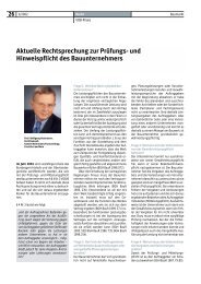
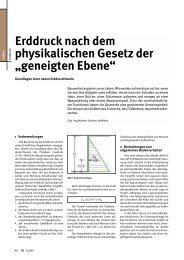
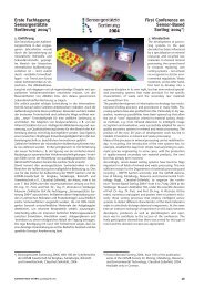
Seitenansicht des <strong>Herdwagenofen</strong>s <strong>mit</strong> geöffnetem Ofentor<br />
Side view of the shuttle kiln with open kiln door<br />
Die Herdwagen sind ebenfalls fast ausschließlich <strong>mit</strong> Keramikfaser<br />
isoliert. Die Wagenumrandung besteht aus relativ dünnwandigen<br />
Cordierit-Profilen, die <strong>mit</strong> Keramikfaser ausgestopft<br />
sind. Das Brenngut ruht auf einem extrem leichten Balkengerüst<br />
aus SiSiC, das von nur wenigen Cordierit-Stützen<br />
getragen wird. Die Stützen sind auf dem Stahlchassis des<br />
Herdwagens fest verankert. Auf eine obere feste Abdeckung<br />
der Faserisolierung, zum Beispiel <strong>mit</strong> Schamotteplatten, wurde<br />
verzichtet.<br />
Durch dieses Konzept sind sowohl die Speichermasse als auch<br />
die Wärmeleitung der Herdwagen minimal.<br />
Brenner <strong>mit</strong> vorgewärmter Verbrennungsluft<br />
Das System gewinnt Wärme aus den Rauchgasen zurück und<br />
stellt diese zum Vorwärmen der Verbrennungsluft zur Verfügung.<br />
Die Temperatur der Verbrennungsluft ist deshalb nicht<br />
konstant, sondern steigt im Laufe des Brennzyklus an. Die Verbrennungsluftversorgung<br />
wurde <strong>mit</strong> einer Frequenzregelung<br />
ausgerüstet, um die Luftverhältnisse für den Brennerbetrieb<br />
konstant zu halten. Die Luftarmaturen sind für die höhere<br />
Temperatur entsprechend ausgelegt. Die Luftversorgung und<br />
die Brenner wurden komplett isoliert.<br />
Durch die höhere Verbrennungslufttemperatur ändern sich<br />
die Strömungsverhältnisse im Zündbereich des Brenners<br />
erheblich. Es war notwendig, die Mischeinrichtung des Brenners<br />
für Gas und Luft anzupassen. Dazu wurden mehrere Versuche<br />
bis zu einer Lufttemperatur von 250 °C durchgeführt –<br />
der korrekt eingestellte Brenner funktioniert bis zu dieser Temperatur<br />
einwandfrei. Höhere Temperaturen konnten noch<br />
nicht ausprobiert werden.<br />
Wärmerückgewinnung aus den Rauchgasen<br />
Ziel ist es, die aus den Rauchgasen zurückgewonnene <strong>Energie</strong>menge<br />
zu maximieren. Die Rauchgase dürfen deshalb<br />
nicht <strong>mit</strong> Frischluft verdünnt, sondern müssen direkt einem<br />
Wärmetauscher zugeführt werden. In der baukeramischen<br />
Industrie können die Rauchgastemperaturen bis zu 1 200 °C<br />
betragen. Ein speziell dafür entwickelter keramischer Wärmetauscher<br />
hält diesen Temperaturen dauerhaft stand. Die Rauchgase<br />
werden darin auf circa 570°C abgekühlt und danach in<br />
einem Edelstahl-Wärmetauscher auf etwa 180 °C bis 200 °C<br />
gebracht. Beide Temperaturen sind regel- und einstellbar.<br />
Die kalte Seite beider Wärmetauscher wird <strong>mit</strong> Frischluft<br />
beaufschlagt, die auf rund 200 °C bis 250 °C erwärmt wird.<br />
38 ZI 3/2003<br />
fibres. The firing charge rests on an extremely lightweight<br />
beam framework of SiSiC, which is supported by only a few<br />
cordierite supports. The supports are firmly anchored to the<br />
steel chassis of the shuttle. A top solid covering of the fibre<br />
insulation, for example with chamotte slabs was dispensed with.<br />
By this concept the body of the storage unit and also the heat<br />
line of the shuttle is minimized.<br />
Burners with preheated combustion air<br />
The system recovers heat from the flue gases and makes this<br />
available for the preheating of the combustion air. The temperature<br />
of the combustion air is therefore not constant, but<br />
increases during the course of the firing cycle. The combustion<br />
air supply was equipped with a frequency regulation system,<br />
in order to keep the air conditions constant for the burner<br />
operation. The air fittings are correspondingly designed for<br />
the higher temperature. The air supply and the burners were<br />
completely insulated.<br />
Due to the higher combustion air temperature the flow conditions<br />
alter considerably in the ignition area of the burner. It<br />
was necessary to adapt the mixing equipment of the burner<br />
for gas and air. For this purpose, several tests were carried out<br />
up to an air temperature of 250° C – the correctly set burner<br />
functions fully efficiently up to this temperature. Higher temperatures<br />
could not yet be tried out.<br />
Heat recovery from the flue gases<br />
The aim is to maximize the amount of energy recovered from<br />
the flue gases. The flue gases should therefore not be diluted<br />
with fresh air, but must be fed directly to a heat exchanger. In<br />
the structural ceramic industry the flue gas temperatures may<br />
amount to 1 200° C. A ceramic heat exchanger specially developed<br />
for the purpose keeps these temperatures permanently<br />
constant. The flue gases are cooled down in this to approx.<br />
570° C and then brought up to about 180° C to 200° C in a<br />
stainless steel heat exchanger. The two temperatures can be<br />
regulated and set.<br />
The cold side of the two heat exchangers is subjected to<br />
impact of fresh air, which is heated up to about 200° C to<br />
250° C. The fresh air, which is conducted via the steel heat<br />
exchanger, is preheated to about 80° C, in order to avoid<br />
exceeding the dewpoints and corrosion on the flue gas side.<br />
The hot air generated is conducted via pipelines to various<br />
dryer systems. Excessive hot air can be blown out via the roof.<br />
Final cooling<br />
During the cooling phase, corresponding to the cooling<br />
curves, normally secondary air is injected into the kiln via the<br />
burners and removed by suction as hot air. The shock cooling<br />
and gentle cooling cause no problems. Rapid final cooling<br />
with the shuttle kiln is more difficult however as here a comparatively<br />
large volume of cooling air is needed. This cannot<br />
be increased at will at reasonable energy expenditure by the<br />
burner openings. Extra injections of cooling air applied must<br />
either be rinsed during the heating, which increases the energy<br />
consumption, or tend to premature corrosion due to<br />
return flowing flue gases.<br />
The shuttles were therefore not sealed with a sand channel,<br />
but with a strip at the side to the kiln body. This sealing strip<br />
can be raised and lowered automatically. In the final cooling<br />
phase the sealing strip can be lowered, so that a great quantity<br />
of fresh air can flow into the kiln at the side. The cooling air<br />
injected to the burners at a high speed divides this fresh air.<br />
Thus a relatively uniform final cooling is obtained in a com-
Die Frischluft, die durch den Stahlwärmetauscher geleitet<br />
wird, ist auf circa 80 °C vorgewärmt, um Taupunktunterschreitungen<br />
und Korrosion auf der Rauchgasseite zu vermeiden.<br />
Die erzeugte Warmluft wird über Rohrleitungen zu<br />
verschiedenen Trockensystemen geleitet. Überschüssige<br />
Warmluft kann übers Dach abgeblasen werden.<br />
Endkühlung<br />
Während der Kühlphase wird, entsprechend der Kühlkurve,<br />
normalerweise Sekundärluft über die Brenner in den Ofen eingeblasen<br />
und als Warmluft abgesaugt. Die Sturzkühlung und<br />
Schonkühlung sind unproblematisch. Eine schnelle Endkühlung<br />
ist aber beim <strong>Herdwagenofen</strong> schwieriger, da hierfür<br />
eine verhältnismäßig große Kühlluftmenge benötigt wird. Diese<br />
kann durch die Brenneröffnungen <strong>mit</strong> vertretbarem <strong>Energie</strong>aufwand<br />
nicht beliebig gesteigert werden. Extra angebrachte<br />
Kühllufteinblasungen müssen entweder während der Aufheizung<br />
gespült werden, was den <strong>Energie</strong>bedarf erhöht, oder<br />
neigen zu vorzeitiger Korrosion durch rückströmende Rauchgase.<br />
Die Herdwagen wurden deshalb nicht <strong>mit</strong> einer Sandrinne,<br />
sondern <strong>mit</strong> einer Leiste seitlich zum Ofenbaukörper abgedichtet.<br />
Diese Abdichtleiste kann automatisch gehoben und<br />
gesenkt werden. In der Endkühlphase kann die Abdichtleiste<br />
gesenkt werden, sodass eine große Menge Frischluft seitlich<br />
am Wagen einströmen kann. Die an den Brennern <strong>mit</strong> hoher<br />
Geschwindigkeit eingeblasene Kühlluft verteilt diese Frischluft.<br />
Da<strong>mit</strong> wird eine relativ gleichmäßige Endkühlung in verhältnismäßig<br />
kurzer Zeit erreicht. Die als Warmluft zurückgewonnene<br />
<strong>Energie</strong>menge wird maximiert, und die Ausfahrverluste<br />
werden minimiert.<br />
Ergebnisse beim Betrieb<br />
Der beschriebene <strong>Herdwagenofen</strong> wird zum Brennen von<br />
Dachziegelzubehör eingesetzt. Das Brennraumvolumen<br />
beträgt circa 140 m 3 , das Gewicht des Besatzguts (gebrannte<br />
Dachziegel plus Kassetten) etwa 34 t. Die Brenntemperatur<br />
liegt bei circa 1 050 °C.<br />
Es wird in 23 Stunden (13 h Heizen, 1 h Haltezeit, 9 h Kühlen)<br />
kalt-kalt gebrannt. Der spezifische <strong>Energie</strong>bedarf beträgt circa<br />
700 kcal (2 900 kJ) pro kg Besatzgut (Dachziegel plus Kassetten).<br />
Die eingesetzte <strong>Energie</strong> kann zu etwa 75 % zurückgewonnen<br />
werden. Der spezifische <strong>Energie</strong>einsatz für den Brand an sich<br />
beträgt also nur circa 175 kcal (725 kJ) pro kg Besatzgut und<br />
liegt da<strong>mit</strong> im Bereich eines Tunnelofens. Allerdings kann die<br />
abgegebene Warmluft nicht immer vollständig in den angeschlossenen<br />
Trockensystemen genutzt werden und muss<br />
dann abgeblasen werden.<br />
Ausblick<br />
Das beschriebene <strong>Herdwagenofen</strong>konzept wurde von Eon<br />
Bayern <strong>mit</strong> einem <strong>Energie</strong>förderpreis für Umweltschutz und<br />
Ressourcenschonung ausgezeichnet. Das Konzept ist weiter<br />
optimierbar. Die Verbrennungsluft könnte beispielsweise <strong>mit</strong><br />
höherer Temperatur bereitgestellt werden, um den <strong>Energie</strong>verbrauch<br />
beim Heizen noch weiter zu senken.<br />
Literatur<br />
[1] Junge, K; Telljohann, U.: Entkopplung von Ofen und Trockner<br />
durch Verbrennungsluftvorwärmung und Zwischenspeicherung<br />
der Verbundwärme, Zi Ziegelindustrie International 55, 8/2002, S.12<br />
bis 22<br />
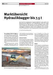
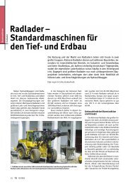
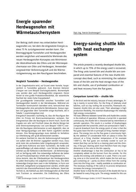
Die Brenner und die Luftversorgung sind komplett isoliert<br />
The burners and the air supply are completely insulated<br />
paratively short time. The energy volume recovered as hot air<br />
is maximized and the exit losses minimized.<br />
Results in operation<br />
The shuttle kiln described is employed for the firing of clay<br />
roofing tile accessories. The firing chamber volume amounts<br />
to approx. 140 m 3 , the weight of the setting charge (fired clay<br />
roofing tiles plus cassettes) about 34 t. The firing temperature<br />
is approx. 1 050° C.<br />
Firing takes place cold-cold in 23 hours (13 hours heating, 1 h<br />
holding time, 9 h cooling). The specific energy consumption<br />
amounts to approx. 700 kcal (2 900 kJ) per kg setting charge<br />
(clay roofing tiles plus cassettes).<br />
The energy used can be recovered up to about 75%. The specific<br />
energy use for firing per se thus amounts to only approx.<br />
175 kcal (725 kJ) per kg setting charge and therefore comes<br />
within the range of a tunnel kiln. However the hot air released<br />
cannot always be completely utilized in the subsequent drying<br />
systems and must then be blown out.<br />
Future prospects<br />
The shuttle kiln concept described was awarded an Energy<br />
Promotion Prize for Environmental Protection and Conservation<br />
of Resources by the Eon Bavaria. The concept is capable<br />
of further optimization. The combustion air could for example<br />
be prepared at a higher temperature, in order to reduce the<br />
energy consumption in heating still further.<br />
Literature references<br />
See German text.<br />
ZI 3/2003<br />
39