Kraftverteilung im Arbeitsspalt von Hochdruck ... - Bauverlag
Kraftverteilung im Arbeitsspalt von Hochdruck ... - Bauverlag
Kraftverteilung im Arbeitsspalt von Hochdruck ... - Bauverlag

Sie wollen auch ein ePaper? Erhöhen Sie die Reichweite Ihrer Titel.
YUMPU macht aus Druck-PDFs automatisch weboptimierte ePaper, die Google liebt.
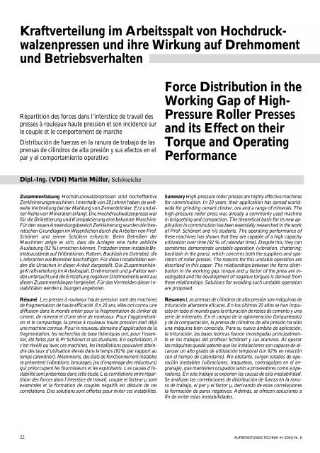
<strong>Kraftverteilung</strong> <strong>im</strong> <strong>Arbeitsspalt</strong> <strong>von</strong> <strong>Hochdruck</strong>walzenpressen<br />
und ihre Wirkung auf Drehmoment<br />
und Betriebsverhalten<br />
Répartition des forces dans l’interstice de travail des<br />
presses à rouleaux haute pression et son incidence sur<br />
le couple et le comportement de marche<br />
Distribución de fuerzas en la ranura de trabajo de las<br />
prensas de cilindros de alta presión y sus efectos en el<br />
par y el comportamiento operativo<br />
Force Distribution in the<br />
Working Gap of High-<br />
Pressure Roller Presses<br />
and its Effect on their<br />
Torque and Operating<br />
Performance<br />
Dipl.-Ing. (VDI) Martin Müller, Schöneiche<br />
Zusammenfassung <strong>Hochdruck</strong>walzenpressen sind hocheffektive<br />
Zerkleinerungsmaschinen. Innerhalb <strong>von</strong> 20 Jahren haben sie weltweite<br />
Verbreitung bei der Mahlung <strong>von</strong> Zementklinker, Erz und einer<br />
Reihe <strong>von</strong> Mineralien erlangt. Die <strong>Hochdruck</strong>walzenpresse war<br />
für die Brikettierung und Kompaktierung eine bekannte Maschine.<br />
Für den neuen Anwendungsbereich Zerkleinerung wurden die theoretischen<br />
Grundlagen <strong>im</strong> Wesentlichen durch die Arbeiten <strong>von</strong> Prof.<br />
Schönert und seinen Schülern erforscht. Be<strong>im</strong> Betreiben der<br />
Maschinen zeigte es sich, dass die Anlagen eine hohe zeitliche<br />
Auslastung (92 %) erreichen können. Trotzdem treten instabile Betriebszustände<br />
auf (Vibrationen, Rattern, Backlash <strong>im</strong> Getriebe), die<br />
Lieferanten wie Betreiber beschäftigen. Für diese Instabilitäten werden<br />
die Ursachen in dieser Arbeit dargestellt. Die Zusammenhänge<br />
<strong>Kraftverteilung</strong> <strong>im</strong> <strong>Arbeitsspalt</strong>, Drehmoment und µ-Faktor werden<br />
untersucht und die Entstehung negativer Drehmomente wird aus<br />
diesen Zusammenhängen hergeleitet. Für das Vermeiden dieser Instabilitäten<br />
werden Lösungen angeboten.<br />
Résumé Les presses à rouleaux haute pression sont des machines<br />
de fragmentation de haute efficacité. En 20 ans, elles ont connu une<br />
diffusion dans le monde entier pour la fragmentation de clinker de<br />
c<strong>im</strong>ent, de minerai et d’une série de minéraux. Pour l’agglomération<br />
et le compactage, la presse à rouleaux haute pression était déjà<br />
une machine connue. Pour le nouveau domaine d’application de la<br />
fragmentation, les recherches de base théoriques ont, pour l’essentiel,<br />
été faites par le Pr Schönert et ses étudiants. En exploitation, il<br />
s’est révélé qu’avec ces machines, les installations pouvaient atteindre<br />
des taux d’utilisation élevés dans le temps (92% par rapport au<br />
temps calendrier). Néanmoins, des états de fonctionnement instables<br />
se présentent (vibrations, broutages; jeu d’engrenage des réducteurs)<br />
qui préoccupent les fournisseurs et les exploitants. Les causes d’instabilité<br />
sont présentées dans cette étude. Les corrélations entre répartition<br />
des forces dans l’interstice de travail, couple et facteur µ sont<br />
examinées et la formation de couples négatifs est déduite de ces<br />
corrélations. Des solutions sont offertes pour éviter ces instabilités.<br />
Summary High-pressure roller presses are highly effective machines<br />
for comminution. In 20 years, their application has spread worldwide<br />
for grinding cement clinker, ore and a range of minerals. The<br />
high-pressure roller press was already a commonly used machine<br />
in briquetting and compaction. The theoretical basis for its new application<br />
in comminution has been essentially researched in the work<br />
of Prof. Schönert and his students. The operating performance of<br />
these machines has shown that they are capable of a high capacity<br />
utilization over t<strong>im</strong>e (92 % of calendar t<strong>im</strong>e). Despite this, they can<br />
somet<strong>im</strong>es demonstrate unstable operation (vibration, chattering;<br />
backlash in the gears), which concerns both the suppliers and operators<br />
of roller presses. The reasons for this unstable operation are<br />
described in this paper. The relationships between the force distribution<br />
in the working gap, torque and µ factor of the press are investigated<br />
and the development of negative torques is derived from<br />
these relationships. Solutions for avoiding such unstable operation<br />
are proposed.<br />
Resumen Las prensas de cilindros de alta presión son máquinas de<br />
trituración altamente eficaces. En los últ<strong>im</strong>os 20 años se han <strong>im</strong>puesto<br />
en todo el mundo para la trituración de restos de cemento y una<br />
serie de minerales. En el campo de la aglomeración (briqueteado)<br />
y de la compactación, la prensa de cilindros de alta presión ha sido<br />
una máquina bien conocida. Para su nuevo ámbito de aplicación,<br />
la trituración, las bases teóricas fueron investigadas principalmente<br />
en los trabajos del profesor Schönert y sus alumnos. Al operar<br />
las máquinas quedó patente que las instalaciones son capaces de alcanzar<br />
un alto grado de utilización temporal (un 92% en relación<br />
con el tiempo de calendario). No obstante, surgen estados de operación<br />
inestables (vibraciones, traqueteos, contragolpes en el engranaje),<br />
que mantienen ocupados tanto a proveedores como a operadores.<br />
En este trabajo se exponen las causas de esta inestabilidad.<br />
Se analizan las correlaciones de distribución de fuerza en la ranura<br />
de trabajo, el par y el factor µ, derivando de estas correlaciones<br />
la formación de pares negativos. Además, se ofrecen soluciones a<br />
fin de evitar estas inestabilidades.<br />
22 AUFBEREITUNGS TECHNIK 44 (2003) Nr. 8
1. Einleitung<br />
Die Durchführung der Zerkleinerung <strong>im</strong> determinierten Gutbett<br />
unter hohem Druck mit <strong>Hochdruck</strong>walzenpressen hat zunächst <strong>im</strong><br />
Bereich der Feinzerkleinerung eine rasante Entwicklung ausgelöst.<br />
Diese gründet sich auf die Energieeffizienz dieses Verfahrens [1,<br />
3, 4]. Da die Maschine, die <strong>Hochdruck</strong>walzenpresse für die Brikettierung<br />
und Kompaktierung, bereits entwickelt war, wurde sie<br />
zunächst ohne größere konstruktive Veränderungen für den neuen<br />
Verwendungszweck übernommen. Die verfahrenstechnischen<br />
Grundlagen zur Auslegung sind bis heute nicht abschließend<br />
untersucht. Die Ursachen für best<strong>im</strong>mte Phänomene (Schwingungen,<br />
Rattern, Blockieren der Walzen, Backlash <strong>im</strong> Getriebe),<br />
die be<strong>im</strong> Betrieb auftreten, sind nicht umfassend geklärt und<br />
beschäftigen Lieferanten und Betreiber. Der Zerkleinerungsprozess<br />
verläuft schnell und auf engstem Raum <strong>im</strong> Spalt zwischen den<br />
Walzen, bei einer Verweildauer <strong>von</strong> etwa 0,1 s. Beobachtung und<br />
messtechnische Erfassung dieses Prozesses sind direkt kaum<br />
durchführbar und würden auch wegen ihres <strong>von</strong> vielen Einflussfaktoren<br />
abhängenden stochastischen Verhaltens schwer auswertbar<br />
und wenig erfolgversprechend sein. Da die vorliegenden<br />
Auslegungsverfahren <strong>im</strong> Durchschnitt zu akzeptablen Ergebnissen<br />
führen, sollte es möglich sein, die Schwierigkeiten durch eine<br />
genauere Untersuchung mit den Mitteln der Mathematik und Physik<br />
zu beseitigen.<br />
2. Kräfteverhältnisse am <strong>Arbeitsspalt</strong><br />
<strong>Hochdruck</strong>walzenpressen ziehen das Aufgabegut zwischen gegenläufig<br />
rotierenden Walzen in den <strong>Arbeitsspalt</strong> ein. Eine der beiden<br />
Walzen ist horizontal beweglich <strong>im</strong> Pressenrahmen gelagert,<br />
während die zweite Walze <strong>im</strong> Rahmen fest angeordnet ist. Die<br />
horizontal bewegliche Walze ist gegenüber dem Pressenrahmen<br />
durch ein hydropneumatisches Federsystem abgestützt. Durch<br />
Einstellung des Öldruckes lässt sich der Anpressdruck der Walzen<br />
einstellen. Die Gesamtpresskraft (F t ) ergibt sich aus dem Öldruck<br />
(P hyd ) und der Summe aller Kolbenflächen (n · A P ) der Arbeitszylinder.<br />
F t<br />
Als spezifische Arbeitsfläche einer Walzenpresse versteht man<br />
das Produkt aus Durchmesser (D) und Arbeitsbreite (B) der Walze<br />
(projizierte Querschnittsfläche senkrecht zur Walzenachse).<br />
F<br />
= n · Ap · P<br />
specf<br />
Ft<br />
=<br />
A<br />
specf<br />
hyd<br />
A<br />
(2)<br />
spcf<br />
= D · B<br />
Der Quotient aus Gesamtpresskraft und spezifischer Arbeitsfläche<br />
wird als spezifische Presskraft bezeichnet.<br />
(1)<br />
(3)<br />
1. Introduction<br />
The introduction of high-pressure roller presses for comminution<br />
in a determinate material bed under high pressure initially triggered<br />
a rapid development in fine comminution. The reason for<br />
this is the energy efficiency of high-pressure comminution in a<br />
determinate material bed [1, 3, 4]. As the high-pressure roller press<br />
had already been developed for briquetting and compaction, at<br />
first it was adopted for the new application without any major<br />
design modifications. The basic process engineering principles for<br />
the design of this machine have not yet been conclusively studied<br />
to this day. The causes of certain phenomena (vibrations, chattering,<br />
locking of the rolls, backlash in the gears) that somet<strong>im</strong>es occur<br />
during operation of high-pressure roller presses have not been<br />
comprehensively explained and concern both the suppliers and<br />
operators of these machines. The comminution process in a highpressure<br />
roller press proceeds quickly and in an extremely confined<br />
space between the rolls, during a material residence t<strong>im</strong>e of around<br />
0.1 s. Direct observation and measurement of this process are<br />
therefore hardly possible and, as the stochastic behaviour of this<br />
process is dependent on many influencing factors, such observations<br />
and measurements would be difficult to evaluate and therefore<br />
not very promising anyway. As the current design procedures<br />
lead on average to acceptable results, it should be possible to tackle<br />
the problems with a more exact study of the machine behaviour<br />
based on a mathematical and physical approach.<br />
2. Forces in the Working Gap<br />
High-pressure roller presses draw the feed material into the gap<br />
between two contra-rotating rolls. One of these two rolls is horizontally<br />
movable in the press frame while the other roll is rigidly<br />
fixed to the frame. The horizontally movable roll is supported<br />
against the press frame by a hydropneumatic spring system. The<br />
press force of the rolls can be adjusted by changing the oil pressure.<br />
The total press force (F t ) results from the oil pressure (P hyd ) and<br />
the sum of all piston areas (n · A P ) of the working cylinders.<br />
F t<br />
The specific working area of a roll press can be described as the<br />
product of the diameter (D) and working width (B) of the roll (projected<br />
cross-sectional area perpendicular to the axis of the roll):<br />
A<br />
= n · Ap · P<br />
spcf<br />
=<br />
D · B<br />
hyd<br />
The quotient of the total press force and the specific working<br />
area is termed the specific press force.<br />
Ft<br />
Fspecf<br />
=<br />
(3)<br />
Aspecf<br />
As can be seen from Fig. 1, the following<br />
applies for each roll:<br />
FN1 = FN2<br />
= Ft·<br />
⋅cos α<br />
for the normal force<br />
2<br />
(1)<br />
(2)<br />
for the tangential force<br />
For further calculations, however, it is more practical to work<br />
with rather than with /2. It is necessary to <strong>im</strong>agine that the torque<br />
and force are applied by one roll. This is justifiable as the following<br />
vector addition shows:<br />
Fig. 2 shows the forces acting in the working gap of the roller press.<br />
Precondition for this is that the hydraulically generated press force<br />
Bild 1: Kräfteverhältnisse am <strong>Arbeitsspalt</strong><br />
Fig. 1: Forces acting in the working gap<br />
F<br />
⎧FNx1 + FNx2<br />
= 0<br />
⎪<br />
+ FN<br />
= ⎨<br />
<br />
⎪FNy1 + FNx2<br />
= Ft ⋅sin ⋅ cos + Ft<br />
⋅sin ⋅cos<br />
⎩<br />
2 2 2 2<br />
N1 2<br />
⎫<br />
⎪<br />
⎬<br />
⎪<br />
⎭<br />
AUFBEREITUNGS TECHNIK 44 (2003) Nr. 8 23
Wie aus Bild 1 zu entnehmen ist, gilt für jede Walze:<br />
F F F<br />
N1 N2<br />
t<br />
2<br />
für die Normalkraft<br />
= = ⋅cos α F t on the line connecting the roll mid-points on the horizontally<br />
für die Tangentialkraft<br />
Für weitere Berechnungen ist es jedoch praktischer mit und nicht<br />
mit /2 zu rechnen. Man geht da<strong>von</strong> aus, dass Drehmoment und<br />
Kraft <strong>von</strong> einer Walze aufgebracht werden, wie folgende Vektoraddition<br />
zeigt:<br />
F<br />
⎧FNx1 + FNx2<br />
= 0<br />
⎫<br />
⎪<br />
⎪<br />
+ FN<br />
= ⎨<br />
⎬<br />
⎪FNy1 + FNx2<br />
= Ft ⋅sin ⋅ cos + Ft<br />
⋅sin ⋅cos<br />
⎪<br />
⎩<br />
2 2 2 2 ⎭<br />
N1 2<br />
⎧Ftgx1 + Ftgx2<br />
= 0<br />
⎫<br />
f<br />
⎪<br />
⎪<br />
+ Ftg<br />
= ⎨<br />
f<br />
f ⎬<br />
⎪Ftgy1 + Ftgy2<br />
= Ft ⋅sin ⋅ cos + Ft<br />
⋅sin ⋅cos<br />
⎪<br />
⎩<br />
2 2 2 2 ⎭<br />
f<br />
Ftg1 2<br />
f<br />
f<br />
FN1 + FN2<br />
= Ft·<br />
• sinα<br />
Ftg 1<br />
+ Ftg2<br />
= Ft<br />
·•<br />
sinα<br />
Bild 2 zeigt die Kräfteverhältnisse am <strong>Arbeitsspalt</strong> der Walzenpresse.<br />
Vorausgesetzt wird, dass die hydraulisch erzeugte Presskraft<br />
F t auf der Verbindungslinie der Walzenmittelpunkte an der<br />
horizontal beweglichen Walze in Richtung auf die Festwalze<br />
angreift. Die Übertragung der Presskraft auf das Mahlgut durch<br />
die sich drehenden Walzen erfolgt <strong>im</strong> <strong>Arbeitsspalt</strong> über die<br />
Berührungsfläche des Mahlgutes und der Walzenoberfläche. Das<br />
Mahlgut wird <strong>im</strong> <strong>Arbeitsspalt</strong> durch die horizontalen Kräfte (Bild 1)<br />
in x-Richtung F A und -F A wie bei einem Pressvorgang belastet.<br />
Gleichzeitig wirkt in y-Richtung die Einzugskraft F Z . Wie aus dem<br />
Schrifttum [11] bekannt, ist die horizontal wirkende Kraft eine<br />
Funktion <strong>von</strong> y (Bild 3) und eine Funktion der Längskoordinate<br />
z in Richtung der Walzenachse. Für die Betrachtungen in diesem<br />
Artikel soll eine zweid<strong>im</strong>ensionale Betrachtung (x-y Ebene) ausreichen<br />
(Mittelwert der Funktionen in z-Richtung)<br />
Die so genannte Grip Force (GF = F tg = sin · F t ) best<strong>im</strong>mt das<br />
Drehmoment. Die y-Komponente der Grip Force ist die Einzugskraft,<br />
die auf das Aufgabegut am Einzugspunkt A wirkt.<br />
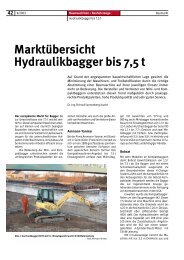
Bild 3: Kraft und Drehmoment (d<strong>im</strong>ensionslos) als Funktion des<br />
Berührungswinkels der Walzenoberfläche und des Mahlgutes<br />
Fig. 3: Force and torque (d<strong>im</strong>ensionless) as a function of the angle<br />
of contact of the roll surface and the product<br />
⎧Ftgx1 + Ftgx2<br />
= 0<br />
⎫<br />
f ⎪<br />
⎪<br />
+ Ftg<br />
= ⎨<br />
f<br />
f ⎬<br />
⎪Ftgy1 + Ftgy2<br />
= Ft ⋅sin ⋅ cos + Ft<br />
⋅sin ⋅cos<br />
⎪<br />
⎩<br />
2 2 2 2 ⎭<br />
f<br />
Ftg1 2<br />
F + F = F·<br />
• sinα<br />
N1 N2<br />
t<br />
F + F = F·<br />
• sinα<br />
tg1 tg2<br />
t<br />
f<br />
f<br />
movable roll is applied in the direction of the fixed roll. The press<br />
force on the product is transmitted by the rotating rolls in the gap,<br />
over the contact surface of the product and the roll surface. In the<br />
gap, the product stressed by the horizontal forces (Fig. 1) in the x-<br />
direction, i.e. F A and – F A , as in a press cycle. At the same t<strong>im</strong>e,<br />
the draw-in force F Z acts in the y-direction. As known from the literature<br />
(11), the force acting in the horizontal is a function of y (see<br />
Fig. 3) and a function of the longitudinal coordinate z in the direction<br />
of the roll axis. For the observations in this paper, a twod<strong>im</strong>ensional<br />
analysis (x-y plane) should be sufficient (mean value<br />
of the functions in the z-direction).<br />
The grip force (GF = F tg = sin · F t ) determines the torque. The<br />
y component of the grip force is the draw-in force acting on the<br />
feed material at draw-in point A.<br />
Bild 2: Details der Kräfte am <strong>Arbeitsspalt</strong><br />
Fig. 2: Details of the forces in the working gap<br />
Bild 4: Scheinbarer Ort der Walze zur Zeit t = 2 für einen mit<br />
dem Mahlgut mitfahrenden Betrachter<br />
Fig. 4: Apparent location of the roll at the t<strong>im</strong>e t = 2 for a product<br />
with a travelling observer<br />
24 AUFBEREITUNGS TECHNIK 44 (2003) Nr. 8
Ausgangspunkt für die weiteren Betrachtungen ist die Untersuchung<br />
des Bewegungsablaufes zwischen Mahlgut (Schülpe) und<br />
Walze. Bei der Walze handelt es sich um eine Rotation und bei der<br />
Bewegung des Mahlgutes durch den Spalt zwischen den Walzen<br />
um eine Translation. Dieser Bewegungsablauf ist für das rollende<br />
Rad bereits eingehend behandelt [2]. Die Bewegungsabläufe zwischen<br />
Mahlgut und Walzen einer <strong>Hochdruck</strong>walzenpresse sind<br />
analog zum rollenden Rad zu betrachten. Der Unterschied besteht<br />
darin, dass das rollende Rad Rotation und Translation gleichzeitig<br />
ausführt und der Boden, auf dem das Rad rollt, feststeht,<br />
während sich in der <strong>Hochdruck</strong>walzenpresse das Mahlgut in Translation<br />
befindet und die Walze (das Rad) <strong>im</strong> Wesentlichen rotiert.<br />
Zunächst gilt es zu klären, wo der Drehpunkt für die gemeinsame<br />
Bewegung <strong>von</strong> Gut und Walze liegt. In Bild 4 ist die Situation für<br />
zwei dicht beieinanderliegende Zeitpunkte der Bewegung<br />
gezeichnet. Das Mahlgut hat sich dabei <strong>von</strong> A* nach A bewegt.<br />
Am Berührungspunkt <strong>von</strong> Walzenoberfläche und Mahlgut bewegen<br />
sich beide mit gleicher Geschwindigkeit (Voraussetzung: kein<br />
Gleiten). Der Berührungspunkt war zum Zeitpunkt t=1 gleich A*<br />
und zum Zeitpunkt t=2 gleich A. Legt man ein Koordinatennetz<br />
mit dem Koordinatenurspung in das Mahlgut und die X-Achse so,<br />
dass A* auf der x-Achse liegt, verschiebt sich bei der Bewegung die<br />
X-Achse <strong>von</strong> A* nach A. Für einen Betrachter, der am Koordinatenursprung<br />
steht und sich mit diesem bewegt, hat sich der Mittelpunkt<br />
der Walzenachse scheinbar <strong>von</strong> M* nach M verschoben.<br />
Nun ist deutlich zu erkennen (Bild 4), dass die Strecke A*A kleiner<br />
ist als die Strecke B*B. Die Drehachse für die gemeinsame<br />
Bewegung ist die Achse parallel zur Walzenachse, die durch den<br />
Punkt A geht und weder <strong>im</strong> Mahlgut noch in der Walze fixiert ist.<br />
Das wird für die Ermittlung der Richtung des Drehmomentes<br />
unter Abschnitt 6 eine wesentliche Rolle spielen.<br />
The starting point for further observations is an investigation of<br />
the motion of the product (flakes) and the roll. The roll rotates<br />
while the motion of the product through the gap between the rolls<br />
can be described as a translation. This motion is dealt with in detail<br />
for the rolling wheel in physics textbooks [2]. The motion of the<br />
product and the rolls in a high-pressure roller press can be regarded<br />
as s<strong>im</strong>ilar to that of the rolling wheel. The difference is that the<br />
rolling wheel performs a rotational and translational motion at the<br />
same t<strong>im</strong>e and the ground on which the wheel rolls is stationary,<br />
while in the high-pressure roller press the product performs a translational<br />
motion (s<strong>im</strong>ilar to the ground in the rolling wheel analogy)<br />
while the roll (the wheel) essentially rotates. First it is necessary<br />
to clarify where the centre of rotation for the joint motion of<br />
the product and the roll lies.<br />
Fig. 4 shows a drawing of this situation for two points in t<strong>im</strong>e of<br />
the motion lying close to each other. In this case, the product has<br />
moved from A* to A. At the point of contact between the roll surface<br />
and the product, both move at the same speed (providing<br />
there is no sliding). The point of contact at t<strong>im</strong>e t=1 was equal to<br />
A* and at t<strong>im</strong>e t=2 equal to A. If a coordinate frame is positioned<br />
so that its origin is in the material and x-axis so that A* lies on the<br />
x-axis, during the motion, the x-axis shifts from A* to A. For an<br />
observer standing at the origin and moving with this, the mid-point<br />
of the roll axis has apparently shifted from M* to M. Now it can be<br />
clearly seen (Fig. 4) that the distance A*A is smaller than the distance<br />
B*B. The rotation coordinate for the joint motion is the axis<br />
parallel to the roll axis that goes through point A and is not fixed<br />
in the product nor in the roll. This plays an essential role in the<br />
determination of the torque direction in Section 7.<br />
Cemtec<br />
AUFBEREITUNGS TECHNIK 44 (2003) Nr. 8 25
3. Berechnung der Leistungsaufnahme einer<br />
<strong>Hochdruck</strong>walzenpresse<br />
Die für die Zerkleinerungsarbeit benötigte Leistung des Antriebes<br />
einer <strong>Hochdruck</strong>walzenpresse berechnet sich wie folgt.<br />
Es gilt aber auch:<br />
P = T · (3)<br />
P = · F · (4)<br />
Das Drehmoment berechnet sich als Vektorprodukt<br />
aus (3) und (4) folgt: T f = F f x r oder T = F · r · sin (5)<br />
T · = · F · (6)<br />
da = r , ergibt sich : F · r · sin r = · F · <br />
und somit gilt: = sin (7)<br />
oder: = F · r · sin = T eff (8)<br />
F · r T max<br />
Die Gleichung (8) zeigt, dass der µ-Faktor das Verhältnis <strong>von</strong><br />
tatsächlich bei der Zerkleinerung in einer Gutbettwalzenpresse<br />
auftretendem zum max<strong>im</strong>al mit der Presskraft (µ =1) erzeugbaren<br />
Drehmoment ist. Der µ-Faktor hat eine ähnlich fundamentale<br />
Bedeutung wie der Wirkungsgrad.<br />
4. Best<strong>im</strong>mung des µ-Faktors<br />
Der µ-Faktor ist mit Gleichung (4) best<strong>im</strong>mbar:<br />
=<br />
F·<br />
P<br />
(9)<br />
Gleichung (9) stellt das Verhältnis der für ein best<strong>im</strong>mtes Mahlgut<br />
erzeugbaren Leistung zur max<strong>im</strong>al mit der Anpresskraft „F“<br />
möglich erzeugbaren Leistung dar.<br />
Mit Gleichung (9) ist die Best<strong>im</strong>mung des µ-Faktors kein Problem,<br />
da alle erforderlichen Größen messbar sind. Für ein Datenerfassungssystem<br />
(wie z. B. dem Data Logger vom Ing. Büro Hübler)<br />
besteht kein Problem, µ online als Trend mit hoher Messfrequenz<br />
darzustellen. Auf diese Weise können unter Betriebsbedingungen<br />
statistisch gesicherte Werte und funktionale Zusammenhänge zu<br />
anderen Größen ermittelt werden.<br />
5. Zusammenhänge mit dem µ-Faktor<br />
Nach Gleichung (7) ist der µ-Faktor gleich dem Sinus des Einzugswinkels.<br />
Wird der <strong>Hochdruck</strong>walzenpresse ofenfallender Klinker aufgegeben,<br />
ergibt sich µ zu etwa 0,08 und damit ein Einzugswinkel<br />
<strong>von</strong> 4,6°.<br />
Bei einem Walzendurchmesser <strong>von</strong> 1 m<br />
und einem <strong>Arbeitsspalt</strong> <strong>von</strong><br />
23 mm<br />
wird bei<br />
4,6° Einzugswinkel<br />
ein Korn <strong>von</strong> 23 mm + 1.000 mm·(1-cos 4,6) = 26,22 mm eingezogen.<br />
Es zeigt sich aber, dass selbst größere aus dem Ofen kommende<br />
Ansatzstücke mit Korngrößen >100 mm <strong>von</strong> Walzen mit 1 m<br />
Durchmesser problemlos erfasst werden. Für diesen Fall müsste<br />
der µ-Faktor bei 0,4 liegen.<br />
Trägt man die bei unterschiedlichen Presskräften erhaltenen µ-<br />
Faktoren als Funktion der Presskraft in ein doppelt logarithmisches<br />
Netz ein, ergibt sich eine Gerade.<br />
Bild 5 zeigt die Abhängigkeit des µ-Faktors <strong>von</strong> der spezifischen<br />
Presskraft (µ = F(F spcf )) für drei unterschiedliche Fälle. Die<br />
Bild 6 gibt die Verhältnisse beispielhaft für die Mahlung <strong>von</strong> Klinker<br />
wieder:<br />
Für das Drehmoment gilt:<br />
T F · A · und damit T A · F · F F<br />
=<br />
specf specf<br />
=<br />
specf specf<br />
= ( specf )<br />
* * sin * * ( )<br />
3. Calculation of the Power Consumption of a<br />
High-Pressure Roller Press<br />
The drive power of a high-pressure roller press for comminution<br />
is calculated as follows.<br />
The following also applies:<br />
P = T · (3)<br />
P = · F · (4)<br />
The torque is calculated as the vector product<br />
from (3) and (4), it follows:<br />
T f = F f x r or T = F · r · sin (5)<br />
T · = · F · (6)<br />
as = r , the following results : F · r · sin r = · F · <br />
and therefore the following applies: = sin (7)<br />
but it is also possible to write: = F · r · sin = T eff (8)<br />
F · r T max<br />
Equation (8) shows that the µ factor is the relationship of<br />
the actually effective torque during comminution in a high-pressure<br />
roller mill to the max<strong>im</strong>um torque that can be generated<br />
with the press force (µ =1). The µ factor has a s<strong>im</strong>ilarly fundamental<br />
significance as the efficiency. It is worth studying this<br />
closer.<br />
4. Determination of the µ Factor<br />
The µ factor can be determined with Equation (9):<br />
=<br />
F·<br />
P<br />
(9)<br />
Eq. (9) represents the relationship of the power that can be generated<br />
when a certain product is handled to the max<strong>im</strong>um power<br />
that can be generated with the press force “F”.<br />
The µ factor can be easily determined with Eq. (9) as the<br />
required variables can all be measured. A data acquisition system<br />
(e.g. the Data Logger from Ing. Büro Hübler) has no problem in<br />
displaying<br />
·<br />
µ online<br />
·<br />
as a trend with high measurement<br />
· ·<br />
frequency.<br />
Bild 5: Abhängigkeit des µ-Faktors <strong>von</strong> der spezifischen Presskraft<br />
für 3 unterschiedliche Materialien<br />
Fig. 5: Dependence of the µ factor on the specific press force for<br />
three different products<br />
26 AUFBEREITUNGS TECHNIK 44 (2003) Nr. 8
In this way, statistically significant values and functional relationships<br />
to other variables · · can be determined and that under operating<br />
conditions.<br />
Bild 6: Funktion µ-F(Fspcf) für Klinker, Kurve 1 für die Vormahlung,<br />
Kurve 2 für die Teilfertigmahlung<br />
Fig. 6: Function µ = F(Fspcf) for clinker, Curve 1 for pre-grinding,<br />
Curve 2 for semi-finish grinding<br />
Die Funktion der Kraft in Abhängigkeit vom Drehwinkel be<strong>im</strong><br />
Passieren des Mahlgutes durch den Walzenspalt wurde mehrfach<br />
best<strong>im</strong>mt und führte zu übereinst<strong>im</strong>menden Ergebnissen [5, 6, 11].<br />
Die größte Kraft wird bei einem Winkel zwischen 1 und 2°<br />
gemessen. Die Funktion lässt sich mathematisch wie folgt beschreiben:<br />
F A B −C<br />
= ⋅e<br />
(10)<br />
Das Problem läuft auf die Best<strong>im</strong>mung der Konstanten A, B<br />
und C hinaus. Von dieser Funktion ist bekannt, dass sich der<br />
Extremwert (Max<strong>im</strong>um) bei<br />
max<br />
=- B C<br />
(11)<br />
5. µ Factor Relationships<br />
According to Eq. (7), the µ factor is the sine of the draw-in angle.<br />
How can this · angle be explained?<br />
If a high-pressure roller press is fed with clinker falling from a<br />
kiln, µ results at around 0.08 and thus gives a draw-in angle of 4.6°.<br />
At a roll diameter of 1 m<br />
a working gap of<br />
23 mm<br />
and at a draw-in angle of 4.6 °<br />
a particle of 23+1000*(1-cos 4,6) = 26.22 mm is drawn in<br />
between the rolls.<br />
Evidently, however, even larger pieces with particle sizes > 100<br />
mm can be easily drawn in by rolls with a diameter of 1 m. In this<br />
case, the µ factor must stand at 0.4. If the different µ factors<br />
obtained at different press forces are plotted as a function of the<br />
press force in a double logarithmic · grid, · a straight line results.<br />
Fig. 5 shows the dependence of the µ factor on the specific press<br />
force (µ = F(Fspcf)) for three different cases. Fig. 6 shows the relationships<br />
for the grinding of clinker as an example:<br />
The following applies for the torque:<br />
T F A und damit · T · A F F F<br />
=<br />
specf specf<br />
=<br />
specf specf<br />
= ( specf )<br />
The function of the force dependent on the angle of rotation as<br />
the product passes through the gap between the rolls has been<br />
determined several t<strong>im</strong>es and concurring results have been<br />
obtained [5,6,11].<br />
The greatest force is measured at an angle between 1 and 2°. The<br />
function can be described mathematically as follows:<br />
F = A<br />
B ⋅e<br />
* * sin * * ( )<br />
−C<br />
(10)<br />
MRS Greifer<br />
AUFBEREITUNGS TECHNIK 44 (2003) Nr. 8 27
ergibt und für max der Winkel zwischen 1 und 2° liegt. Damit ist<br />
das Verhältnis B/C fix.<br />
Normiert man die Gleichung (10) mit dem Wert für die bei max<br />
auftretenden Kraft (Max<strong>im</strong>alkraft), erhält man folgende Gleichung:<br />
1<br />
B -C<br />
FN = e<br />
(12)<br />
B -B<br />
* *· *·<br />
max · e<br />
Für das Drehmoment muss gelten (Walzendurchmesser =1m):<br />
T ∫ F <br />
·<br />
*<br />
d<br />
<br />
= ( )<br />
(13)<br />
Das best<strong>im</strong>mte Integral der Gleichung (10) in den Grenzen <strong>von</strong><br />
0 bis strebt einem Grenzwert zu. Dieser Grenzwert stellt das<br />
2<br />
d<strong>im</strong>ensionslose Drehmoment des mit Aufgabegut gefüllten Zwischenraumes<br />
zwischen den Walzen dar. Das best<strong>im</strong>mte Integral in<br />
den Grenzen <strong>von</strong> 0 bis der normierten Gleichung (12) ist aber<br />
2<br />
auch der µ- Faktor. Er kann als das d<strong>im</strong>ensionslose Drehmoment<br />
aufgefasst werden, mit dem die Presskraft zu multiplizieren ist, um<br />
das zugehörige Drehmoment (Walzendurchmesser = 1 m) zu<br />
erhalten.<br />
Beispiel: Aus der Betriebserfahrung oder aus Versuchen wurde<br />
der µ-Faktor einer Teilfertigmahlung mit 0,095 best<strong>im</strong>mt. Da B<br />
aus mathematischen Überlegungen zwischen 0 und 1 liegen muss,<br />
ergibt sich<br />
<br />
2<br />
für =∫F<br />
( ) ⋅ d<br />
= 0 ,<br />
N<br />
095 und für (14)<br />
0<br />
F 1<br />
(15)<br />
e<br />
-047 , -21,<br />
15<br />
N( )= * * e<br />
-<br />
0 022 047 , 047 , · ·<br />
, *·<br />
In Bild 5 und 6 sind die Funktionen dargestellt, sowohl allgemein<br />
gültig d<strong>im</strong>ensionslos als auch für einen angenommenen Betriebsfall<br />
Walzenpresse mit 1 m 2 spezifischer Arbeitsfläche und<br />
6.000 kN/m 2 spezifischer Presskraft.<br />
6. Erkenntnisse aus den bisherigen Überlegungen<br />
• Der µ-Faktor, wie er bei der D<strong>im</strong>ensionierung <strong>von</strong> <strong>Hochdruck</strong>walzenpressen<br />
für die Zerkleinerung verwendet wird, ist das<br />
best<strong>im</strong>mte Integral der normierten Kraft als Funktion des<br />
Angriffswinkels F N() in den Grenzen <strong>von</strong> 0 bis . Das bedeutet,<br />
dass der µ-Faktor abn<strong>im</strong>mt, wenn z. B. durch Verringerung<br />
2<br />
der Beschickung der Füllungsgrad des Raumes zwischen den<br />
Walzen verringert wird oder wenn der beginnende Einzug des<br />
Aufgabegutes bei einem kleineren Winkel stattfindet.<br />
• Jeder Betreiber kennt das Problem, dass während des Anfahrens<br />
und Abfahrens die Schwankungen des Drehmomentes zunehmen<br />
und oft unzulässige Werte erreicht werden. Die Stammfunktion<br />
(das unbest<strong>im</strong>mte<br />
Integral) der Funktion F N()<br />
ändert ihren Wert <strong>im</strong> Bereich<br />
des voll gefüllten Zwischenraumes<br />
zwischen den<br />
Walzen bei einer Füllungsgradänderung<br />
nur geringfügig.<br />
Wird dieser jedoch klein<br />
gehalten, rufen schon geringe<br />
Änderungen der Aufgabegutmenge<br />
große Änderungen<br />
des µ-Faktors (des Drehmomentes)<br />
hervor. Der Grund<br />
hierfür ist der Verlauf der<br />
Kennlinie (Bild 7 und 8).<br />
7. Das Auftreten negativer<br />
Drehmomente<br />
Das Auftreten <strong>von</strong> Schwingungen<br />
des Drehmomentes mit<br />
The problem comes down to the determination of the constants<br />
A, B and C. From this function it is known that the extreme value<br />
(max<strong>im</strong>um) is calculated as<br />
max<br />
=- B (11)<br />
C<br />
For, it is known that the angle lies between 1 and 2°. The ratio<br />
B/C is then fixed.<br />
If function (10) is normalized with the value for the force (max<strong>im</strong>um<br />
force) generated at (max<strong>im</strong>um force), the following equation<br />
is obtained.<br />
F<br />
1<br />
B<br />
e<br />
* *· *·<br />
max · e<br />
N<br />
=<br />
B -B<br />
(12)<br />
The equation for the torque (with a roll diameter = 1 m) must be:<br />
T ∫F *· d<br />
= ( )<br />
(13)<br />
The definite integral of function (10) within the l<strong>im</strong>its from 0 to<br />
<br />
approaches a l<strong>im</strong>it value. This l<strong>im</strong>it value represents the d<strong>im</strong>ensionless<br />
torque of the space between the rolls (with a diameter of<br />
2<br />
1 m) filled with feed material. The determined integral within the<br />
l<strong>im</strong>its from 0 to of the normalized function (12) is, however, also<br />
2<br />
the µ factor. It can be explained as the d<strong>im</strong>ensionless torque with<br />
which the press force must be multiplied to obtain the associated<br />
torque (roll diameter = 1 m).<br />
Example: From practical experience or operating trials, the µ<br />
factor of a semi-finish grinding process has been calculated as<br />
0.095. As, based on mathematical considerations, B must lie<br />
between 0 and 1, the following results<br />
<br />
2<br />
for =∫FN ( ) ⋅ d<br />
= 0,<br />
095 and for (14)<br />
0<br />
F 1<br />
(15)<br />
e<br />
-047 , -21,<br />
15<br />
N( )= *· *·<br />
e<br />
-<br />
0 022 047 , 047 ,<br />
, *·<br />
In Figs. 5 and 6, the functions are shown, firstly as d<strong>im</strong>ensionless<br />
and universally valid, and secondly for an assumed case involving<br />
a roller press with 1 m 2 specific working area and 6000 kN/m 2 specific<br />
press force.<br />
6. What Findings can be Derived from these<br />
Considerations<br />
• The µ factor used for d<strong>im</strong>ensioning high-pressure roller presses<br />
for comminution is the definite integral of the normalized force<br />
as a function of the angle of force application F N() within the<br />
l<strong>im</strong>its of 0 to 2<br />
-C<br />
Bild 7: Krafteinleitung und Drehmomentverlauf (d<strong>im</strong>ensionslos)<br />
für den <strong>Arbeitsspalt</strong> <strong>von</strong> <strong>Hochdruck</strong>walzenpressen für einen mittleren<br />
µ-Faktor = 0,095<br />
Fig. 7: Power input and torque curve (d<strong>im</strong>ensionless) for the<br />
working gap of high-pressure roller presses for a mean µ factor =<br />
0.095<br />
. That means that the µ factor becomes lower when<br />
the material filling in the space<br />
between the rolls decreases, for<br />
example as a result of a lower<br />
feed rate, or when the feed<br />
material is drawn in at a smaller<br />
angle at the beginning.<br />
• Every operator is familiar<br />
with the problem of increased<br />
variation of the torque during<br />
machine start-up and shutdown,<br />
the torque then often<br />
exceeding the permissible<br />
values. If the space between<br />
the rolls is full or almost full,<br />
the value of the anti-derivative<br />
(the indefinite integral)<br />
of the function changes only<br />
slightly in response to a<br />
change in the filling degree. If<br />
the filling degree within the<br />
28 AUFBEREITUNGS TECHNIK 44 (2003) Nr. 8
Amplituden, die über den positiven<br />
Bereich des Drehmomentes<br />
[7, 8, 12, 13, 14] hinausgehen,<br />
stellen einen schwerwiegenden<br />
Störfall dar, da eine<br />
Richtungsumkehr des Drehmomentes<br />
verbunden mit einer<br />
Drehrichtungsumkehr auftritt.<br />
Wie Gleichung (5) zeigt, ist dies<br />
entscheidend vom Kraftangriffswinkel<br />
abhängig. Die<br />
Drehrichtung einer am Faden<br />
gezogenen Garnrolle kann sich<br />
bei gleicher Richtung der ziehenden<br />
Kraft dadurch ändern,<br />
dass sich der Angriffswinkel<br />
der Kraft ändert [2]. Die Garnrolle<br />
rollt auf den Ziehenden zu<br />
oder <strong>von</strong> ihm weg, obwohl sich<br />
an der Richtung der ziehenden<br />
Kraft nichts geändert hat. Liegt in der Nähe <strong>von</strong> 0°, können leicht<br />
negative Winkel (Rückdehnung der Schülpe) kurzzeitig auftreten,<br />
damit wird sin negativ und somit das Drehmoment (T) negativ.<br />
T<br />
= F⋅r⋅sinα<br />
Für den normalen Betriebsfall der <strong>Hochdruck</strong>walzenpresse mit<br />
stabiler Schülpenbildung und kontinuierlicher Beschickung mit<br />
Aufgabegut gelten die Beziehungen <strong>von</strong> Bild 9.<br />
Für den Fall des nur teilweise mit Schülpe (Aufgabegut) gefüllten<br />
Spaltes gelten andere Verhältnisse. Wie zu beobachten ist,<br />
kann es bei der gedrosselten Beschickung zum sogenannten<br />
„Verhungern“ des <strong>Arbeitsspalt</strong>es kommen. Die Schülpenbildung<br />
setzt kurzzeitig aus. Man muss da<strong>von</strong> ausgehen, dass in diesen<br />
Fällen <strong>im</strong> <strong>Arbeitsspalt</strong> unterhalb des mittleren Einzugswinkels<br />
kurzzeitig der Druck für eine Schülpenbildung nicht ausreicht,<br />
und das feinkörnige Gut aus dem Spalt herausfällt. Das entsteht<br />
bei einer Fahrweise, die durch Drosselung der Aufgabemenge<br />
den Kraftangriffswinkel klein hält. Wird die Aufgabemenge<br />
größer, weil die Dosierung nicht konstant ist oder weil das Aufgabegut<br />
Einzelkörner enthält, die sehr viel größer als das mittlere<br />
Korn sind, dann wandert der Kraftangriffspunkt „A“ – wie in<br />
Bild 10 gezeigt – in Richtung größerer Kraftangriffswinkel. Das<br />
führt zu einer Richtungsumkehr des Drehmomentes und zum<br />
Schließen des <strong>Arbeitsspalt</strong>es. Da sich die angreifende Kraft für<br />
Bild 8: Krafteinleitung und Drehmomentverlauf für den <strong>Arbeitsspalt</strong><br />
einer <strong>Hochdruck</strong>walzenpresse für einen mittleren µ-Faktor<br />
= 0,095 Beispiel F spcf = 6000 kN/m 2 ; A spcf =1m 2<br />
Fig. 8: Force input and torque curve for the working gap of a high<br />
pressure roll press for a mean µ factor = 0.095 Example F spcf =<br />
6000 kN/m 2 ; A spcf = 1 m 2<br />
space between the rolls is,<br />
however, kept low, even slight<br />
changes in the rate of the material<br />
feed to the machine result<br />
in large changes in the µ factor<br />
(i.e. in the torque). The reason<br />
for this is a change in the gradient<br />
of the characteristic curve<br />
(Figs. 7 and 8).<br />
7. Generation of Negative<br />
Torques<br />
Torque vibrations with amplitudes<br />
exceeding the positive<br />
range of the torque [7, 8, 12, 13,<br />
14] cause serious problems.<br />
How can a reversal in the direction<br />
of the torque in connection<br />
with a reversal in the direction<br />
of rotation be explained. As<br />
Eq. (5) shows, the direction of the torque is crucially dependent on<br />
angle of force application. As described in physics textbooks, the<br />
direction of rotation of a bobbin of thread pulled by the thread can<br />
change even though the direction of the pulling force has not been<br />
changed. This change in the rotational direction of the bobbin is<br />
caused by a change in the angle of the force application. The bobbin<br />
of thread rolls towards or away from the person pulling the<br />
thread although the person has not changed the direction in which<br />
he is pulling the thread. If lies near 0°, slightly negative angles<br />
(elastic relaxation of the flakes) can occur for a short t<strong>im</strong>e and thus<br />
sin and therefore also the torque (T) become negative<br />
T<br />
= F⋅r⋅sinα<br />
For the normal operation of a high-pressure roller press with stable<br />
flake formation and a continuous supply of feed material, the<br />
relationships in Fig. 9 apply.<br />
Other relationships apply if the gap is only partly filled with<br />
flakes (feed material). As can be observed, a choked feed can<br />
lead to „starvation“ of the gap. Flake formation stops for a short<br />
t<strong>im</strong>e. It must be assumed in these cases that the pressure applied<br />
in the gap below the mean draw-in angle is temporarily insufficient<br />
to enable the formation of flakes and the fine-grained material<br />
s<strong>im</strong>ply falls out of the gap. This can happen in an operating<br />
mode that keeps the angle of force application small by choking<br />
the feed. If the feed rate increases, because metering of the mate-<br />
F tg =F t·sin<br />
F tg = Kraftkomponente der<br />
Presskraft, die zur<br />
Drehmomenterzeugung<br />
einen Beitrag<br />
liefert./Force component<br />
of the press force, which<br />
contributes to the generation<br />
of the torque.<br />
F 1 = Presskraft/Press force<br />
= Kraftangriffswinkel/ Angle<br />
of force application<br />
A = Drehpunkt für Koordinationssystem<br />
fest <strong>im</strong> Gut<br />
(bewegt)/Centre of rotation<br />
of the coordinate system<br />
fixed in the product<br />
(moved)<br />
M= Drehpunkt der Walze/<br />
Centre of the roll<br />
rotation<br />
F f tg = F f tg1 +F f tg2<br />
F f tg1 = erzeugt negatives<br />
Drehmoment/generates<br />
negative torque<br />
F f tg2 = erzeugt positives<br />
Drehmoment/generates<br />
positive torque<br />
F f<br />
= F t1+F t2 Presskraft<br />
= Kraftangriffswinkel/Angle<br />
of force application<br />
A = Drehpunkt/Contre of<br />
rotation<br />
Bild 9: Drehmomenterzeugung bei kontinuierlicher Beschickung<br />
und Abstützung der Walzen <strong>im</strong> Mahlgut (in der Schülpe)<br />
Fig. 9: Development of the torque with continuous feed and support<br />
of the rolls in the product (the flakes)<br />
Bild 10: Drehmomenterzeugung bei diskontinuierlicher Beschickung<br />
und Abreißen der Schülpenbildung<br />
Fig. 10: Generation of the torque with intermittent feed and interruption<br />
in the flake formation<br />
AUFBEREITUNGS TECHNIK 44 (2003) Nr. 8 29
diesen Fall durch Addition der Vektoren der Teilkräfte F f tg= F f tg1 +<br />
F f tg2 ergibt, kann F f tg2 = 0 werden, dann beträgt das Gegenmoment<br />
F f tg= F f tg1 = F t · sin .<br />
Dieses Gegenmoment dreht die Walzen rückwärts. Das erklärt,<br />
weshalb <strong>Hochdruck</strong>walzenpressen besonders bei An-und Abfahrprozessen<br />
oder bei gedrosselter Aufgabegutmenge zu Vibrationen<br />
(Schwingungen) neigen. Das Auftreten negativer Drehmomente<br />
ist auch mit der <strong>Kraftverteilung</strong>sfunktion zu erklären. Bild 11 zeigt<br />
den Fall, dass die Schülpenbildung bei einem Winkel <strong>von</strong> 4°<br />
(0,07rad) aussetzt und der Spalt leer wird. Die Integration der<br />
<strong>Kraftverteilung</strong>sfunktion (F/F max ) erfolgt vom Punkt 4° auf der<br />
Abzisse und ergibt negative Werte für den Bereich < 4° und positive<br />
Werte für den Bereich > 4°.<br />
T = = ∫ F ( )⋅ d<br />
=0,<br />
020<br />
1<br />
T = = ∫ F ( )⋅ d<br />
= −0,<br />
075<br />
2<br />
<br />
2<br />
007 ,<br />
0<br />
007 ,<br />
N<br />
N<br />
Das Drehmoment T 2 ist das best<strong>im</strong>mte Integral <strong>von</strong> 0,07 (4°) bis<br />
0 und ist negativ. T 1 ist positiv. Das resultierende Drehmoment ist<br />
wegen /T 1 />/T 2 / negativ.<br />
T = T 1 +T 2<br />
Für das Beispiel beträgt T = –0,055 für F spcif = 6000kN/m 2 und<br />
D = 1m folgt:<br />
T = -330 kNm.<br />
rial is not constant or because the feed material contains single<br />
particles that are very much larger than the mean particle size, the<br />
point of force application “A” shifts towards larger angles of force<br />
application. That means that the force is applied as shown in Fig.<br />
8. This leads to a reversal of the torque direction and closing of<br />
the gap. As the applied force in this case results from the addition<br />
of the vectors of the force components F f tg= F f tg1 + F f tg2 can<br />
become equal to zero, and then the countertorque is F f tg= F f tg1=<br />
F t · sin .<br />
This countertorque causes the rolls to rotate backwards. That<br />
explains why high-pressure roller presses tend to suffer vibrations<br />
particularly during start-up or shutdown or with a choked feed rate.<br />
The occurrence of negative torques can also be explained with the<br />
force distribution function. Fig. 11 shows the case of flake formation<br />
stopping at an angle of 4° (0.07 rad) and the gap being emptied.<br />
The force distribution function (F/F max ) is integrated from<br />
point 4° on the x-axis and results in negative values for the range<br />
< 4° and positive values for the range > 4°.<br />
T = = ∫ F ( )⋅ d<br />
=0,<br />
020<br />
1<br />
T = = ∫ F ( )⋅ d<br />
= −0,<br />
075<br />
2<br />
<br />
2<br />
007 ,<br />
0<br />
007 ,<br />
N<br />
N<br />
The torque T 2 is the definite integral from 0.07 (4°) to 0 and is negative.<br />
T 1 is positive. The resulting torque is negative on account of<br />
/T 1 />/T 2 /.<br />
T = T 1 +T 2<br />
For the example, T = –0.055, for F spcif = 6000 kN/m 2 and D = 1 m<br />
it follows:<br />
Bild 11: Drehmomenterzeugung (Kurve INT (F/Fmax) bei nichtkontinuierlicher<br />
Beschickung und Abreissen der Schülpenbildung<br />
bei 4°<br />
Fig. 11: Generation of the torque (curve INT (F/Fmax) with intermittent<br />
feed and interruption of flake formation at 4°<br />
Lubjuhn [11] hat für die Funktion der Kraft in Abhängigkeit<br />
vom Drehwinkel gefunden, dass infolge <strong>von</strong> Rückdehnungen der<br />
Schülpe negative Drehwinkel möglich sind. Bild 12 zeigt einen<br />
angenommenen Verlauf der d<strong>im</strong>ensionslos gemachten Kraft als<br />
Funktion des Drehwinkels unter Beachtung <strong>von</strong> Rückdehnungen<br />
der Schülpe.<br />
Bild 13 zeigt den zugehörigen Drehmomentverlauf. Auch hier<br />
besteht die Möglichkeit des Auftretens negativer Drehmomente,<br />
wenn der <strong>Arbeitsspalt</strong> nur gering gefüllt ist (sogenannter „verhungerter“<br />
Spalt). Die Gefahr, dass negative Drehmomente be<strong>im</strong><br />
„Verhungern“ des Spaltes auftreten, wird um so wahrscheinlicher,<br />
je größer der Wert der Rückdehnung ist. Im dargestellten Fall tritt<br />
ein Blockieren der Walzen bei einer Füllung des <strong>Arbeitsspalt</strong>es<br />
Bild 12: <strong>Kraftverteilung</strong> für den Fall des Auftretens <strong>von</strong> Schülpenexpansion<br />
(Rückdehnung: Funktion beginnt bei negativen Winkeln.)<br />
Fig. 12: Force distribution when flake expansion occurs (elastic<br />
relaxation: function begins at negative angles)<br />
T = -330 kNm.<br />
For the function of the force dependent on the angle of rotation,<br />
Lubjuhn [11] has found that the elastic relaxation of the flakes can<br />
lead to negative angles of rotation. Fig. 12 shows an assumed curve<br />
of the d<strong>im</strong>ensionless force as a function of the angle of rotation<br />
with allowance for the elastic relaxation of the flakes.<br />
Fig. 13 shows the associated torque curve. Here too, negative<br />
torques may result if the gap is only filled with a small quantity<br />
of material (“starved” gap). The danger of the occurrence of<br />
negative torques during starving of the gap becomes all the<br />
30 AUFBEREITUNGS TECHNIK 44 (2003) Nr. 8
unter etwa 1,5° ein. Die Walzen<br />
werden mit einem Drehmoment<br />
<strong>von</strong> T = –120 kNm (F spcif<br />
= 6000kN/m 2 und D = 1m) in<br />
die Gegenrichtung gedreht,<br />
wenn der <strong>Arbeitsspalt</strong> bis zu<br />
seiner engsten Stelle entleert<br />
wird.<br />
Es existieren zwei instabile<br />
Bereiche für den Antrieb:<br />
• Entleeren des <strong>Arbeitsspalt</strong>es,<br />
beginnend <strong>von</strong> der Eintragsseite<br />
durch zu geringe Beschickung.<br />
• Entleeren des <strong>Arbeitsspalt</strong>es,<br />
beginnend <strong>von</strong> der Austragsseite<br />
durch Instabilität der<br />
Schülpe.<br />
In Bild 14 ist dargestellt, wie<br />
das Gesamtdrehmoment (T1 +<br />
T2) abn<strong>im</strong>mt, wenn der Spalt<br />
bei Winkeln unterhalb des Aufstandpunktes<br />
(A) entleert wird.<br />
Für A soll ein µ-Faktor <strong>von</strong><br />
0,095 oder = 5,45° gelten.<br />
Bild 13: Drehmomentverteilung für den Fall des Auftretens <strong>von</strong><br />
Schülpenexpansion (Rückdehnung: Funktion bei negativen Winkeln.)<br />
Fig. 13: Torque distribution when flake expansion occurs (elastic<br />
relaxation: function begins at negative angles)<br />
Im Schrifttum werden Vibrationen (Schwingungen) der <strong>Hochdruck</strong>walzenpressen<br />
auf Torsionsschwingungen des Antriebssystems<br />
zurückgeführt. Das ist zweifellos so, erklärt aber nicht, wie die<br />
für jede Schwingungserzeugung notwendigen Kraftstöße erzeugt<br />
werden. Der E-Motor spannt die Torsionsfeder (Antriebswellen)<br />
vor. Bei einem Aussetzen der Beschickung und sich langsam entleerendem<br />
Spalt müsste es zu einer Beschleunigung der Drehzahl<br />
kommen, da die Torsionsspannung in Richtung des Antriebsmomentes<br />
wirkt. Das Gegenteil tritt ein. Zunächst fällt das Drehmomore<br />
probable the larger the<br />
value for the elastic relaxation<br />
of the flakes is. In the case<br />
described (Fig. 13), the rolls<br />
become locked at a gap filling<br />
below around 1.5°. The rolls<br />
are rotated at torques of T =<br />
–120 kNm (F spcif = 6000<br />
kN/m 2 und D = 1 m) in the<br />
opposite direction when the<br />
gap is emptied to its narrowest<br />
point.<br />
There are two unstable<br />
ranges for the drive:<br />
• emptying of the gap beginning<br />
from the draw-in side as<br />
a result of an excessively low<br />
(choked)feed rate.<br />
• emptying of the gap beginning<br />
from the discharge side<br />
as a result of flake instability.<br />
Fig. 14 shows how the total<br />
torque (T1 + T2) decreases<br />
when the gap becomes empty<br />
at angles below the contact<br />
point (A). A µ factor of 0.095 or = 5.45° should apply for A.<br />
In the literature, vibrations of the high-pressure roller presses<br />
are attributed to the torsional vibrations of the drive system.<br />
Although this is doubtlessly the case, it does not explain how the<br />
<strong>im</strong>pulses necessary to excite each vibration are generated. The<br />
electric motor pre-loads the torsion springs (drive shafts). If the<br />
material feed is stopped and the gap between the rolls slowly empties,<br />
the speed should accelerate as the torsional stress acts in the<br />
direction of the driving torque. The opposite happens. First the<br />
STC<br />
Narlin<br />
AUFBEREITUNGS TECHNIK 44 (2003) Nr. 8 31
Bild 14: Drehmomenterzeugung bei diskontinuierlicher Beschickung<br />
in Abhängigkeit vom Winkel des Abreißpunktes der<br />
Schülpenbildung.<br />
Fig. 14: Generation of the torque with intermittent feed as a function<br />
of the angle of the point of interruption in flake formation<br />
ment ab (fallender Trend) und erst dann treten Schwingungen mit<br />
Backlash auf. Dabei zeigen die Walzen kurzzeitige Stillstände in der<br />
Drehbewegung und bei schweren Vibrationen ein kurzes Rückwärtsdrehen<br />
an. Ein Rückwärtsdrehen – hervorgerufen durch Torsionsspannungen<br />
des Antriebes – kann nur erfolgen, wenn die<br />
Kupplung wegen Überlast auslöst. Das führt aber zu keinen<br />
Schwingungen.<br />
Einen anderen Fall <strong>von</strong> Schwingungen beschreibt Schmitz [10].<br />
Dieser Fall tritt bei der Feinmahlung auf. Nach eigenen Beobachtungen<br />
verläuft die Entwicklung der Schwingung in diesem Fall<br />
wie folgt:<br />
Mit feiner werdendem Aufgabegut, z. B. bei der Teilfertigmahlung<br />
durch Steigerung der Sichterdrehzahl, wird der µ-Faktor<br />
zunächst größer und die Dicke sowie die Dichte der Schülpe<br />
(Spalt) nehmen zu. Kann die Schülpe der erhöhten Belastung nicht<br />
mehr standhalten, z. B. durch Lufteinschlüsse oder weil sie zu dick<br />
geworden ist, dann ist <strong>im</strong> Bereich des engsten Abstandes der Walzen<br />
(Punkt B, Bild 1) keine Gegenkraft zur Auflagekraft F A vorhanden,<br />
und die Drehrichtung der Walze wechselt in die Gegenrichtung.<br />
Es kommt zum Kraftstoß und die Schwingung wird ausgelöst.<br />
Bild 15 zeigt den Karftverlauf <strong>im</strong> <strong>Arbeitsspalt</strong> und den<br />
zugehörigen Drehmomentverlauf für unterschiedliche Abreißpunkte<br />
der Schülpenbildung. Für Abreißwinkel >3° gibt es kein<br />
positives Drehmoment.<br />
8. Schlussfolgerungen<br />
Für das Verhindern der oben beschriebenen negativen Betriebszustände<br />
<strong>von</strong> <strong>Hochdruck</strong>walzenpressen ergeben sich Forderungen<br />
an die Betriebsweise und die Ausrüstung <strong>von</strong> Anlagen zur Zerkleinerung,<br />
die mit <strong>Hochdruck</strong>walzenpressen arbeiten.<br />
Die Beschickung der <strong>Hochdruck</strong>walzenpresse muss regelbar<br />
sein. Einerseits muss stets soviel Gut zugeführt werden, wie der<br />
Walzenspalt zu jedem Zeitpunkt entsprechend der zeitlich veränderlichen<br />
Einzugsbedingungen benötigt, und andererseits müssen<br />
die Einzugsbedingungen beeinflusst werden können. Das gilt<br />
besonders für An- und Abfahrprozesse und für Betriebszustände,<br />
die zu sehr dicken und dichten Schülpen bei feinkörnigem Aufgabegut<br />
führen. Die Veränderung der Walzendrehzahl kann nur<br />
den Durchsatz beeinflussen. Die elektrische Leistungsaufnahme<br />
verändert sich dann proportional zum Durchsatz. Das Drehmoment<br />
wird dabei nicht verändert und somit besteht auch kein Einfluss<br />
auf die Einzugsbedingungen. Regelungskonzepte, die <strong>von</strong><br />
einer Drehzahlbeeinflussung ausgehen, können keinen Erfolg<br />
haben. Größte Bedeutung kommt der Wahl der spezifischen Presskraft<br />
zu, da sie einen Einfluss auf den Kraftangriffswinkel, das<br />
Drehmoment und die max<strong>im</strong>ale Presskraft <strong>im</strong> Spalt hat. Durch die<br />
Wahl der spezifischen Arbeitsfläche der Walzen wird durch den<br />
Bild 15: Drehmomenterzeugung bei nichtkontinuierlicher Beschickung<br />
und Abreißen der Schülpenbildung (Parameter: Winkel<br />
des Abreißpunktes)<br />
Fig. 15: Generation of the torque with intermittent feed and interruption<br />
in flake formation (parameter: angle of the point of interruption)<br />
torque decreases (falling trend) and only then do vibrations with<br />
backlash occur. The rolls temporarily stop rotating and, if the<br />
vibrations are very strong, they may even rotate backwards for a<br />
short t<strong>im</strong>e. A reversed rotation can only be caused by torsional<br />
stresses of the drive if the clutch releases as a result of overload.<br />
This does not lead to any vibrations.<br />
Schmitz [10] describes another instance of vibrations. These are<br />
generated during fine grinding. According to the author’s own<br />
observations, in this case the vibrations develop as follows:<br />
With increasingly fine feed material, e.g. during semi-finish<br />
grinding based on a higher classifier speed, the µ factor initially<br />
becomes larger and the thickness of the flake (gap) increases; the<br />
density of the flake increases at the same t<strong>im</strong>e. If the flake is no<br />
longer able to withstand the increased load, e.g. owing to<br />
entrapped air or because it has become too thick, then in the region<br />
of the narrowest distance between the rolls (point B, Fig. 1) there<br />
is no force to counter the load pressure FA, and the direction of<br />
roll rotation reverses. This results in an <strong>im</strong>pact force and a vibration<br />
is excited. Fig. 15 shows the pattern of force in the working gap<br />
and the associated torque curve for different points of interruption<br />
in flake information. For interruption angles >3°, there is no positive<br />
torque.<br />
8. Conclusions<br />
To prevent the negative operating states of high-pressure roller<br />
presses described above, the operation and equipment of comminution<br />
plants incorporating high-pressure roller presses must<br />
meet certain requirements.<br />
The feed to the high-pressure roller press must be controllable.<br />
On the one hand, as much material must always be supplied to the<br />
gap as this requires at each point in t<strong>im</strong>e depending on the changing<br />
material draw-in conditions. On the other hand, it must be possible<br />
to influence the material draw-in conditions. This applies particularly<br />
to the start-up and shutdown phases as well as operating<br />
modes that lead to very thick and dense flakes when the press is<br />
handling fine-grained feed material. Changing the speed of the<br />
rolls can only influence the throughput rate. The electric power<br />
consumption then changes proportionally to the throughput rate.<br />
The torque is not changed in this process and therefore the conditions<br />
of the draw-in the feed material are not influenced. Control<br />
concepts based on influencing operation by adjustment of the<br />
speed of the rolls cannot be successful therefore.<br />
The selection of the specific press force is of the greatest <strong>im</strong>portance,<br />
as this influences the angle of force application, the torque<br />
and the max<strong>im</strong>um press force in the gap. By selection of the specific<br />
working surface of the roll, the suppliers also define the specific<br />
press force. Design errors here are paid for with machine<br />
32 AUFBEREITUNGS TECHNIK 44 (2003) Nr. 8
Lieferanten auch die spezifische Presskraft vorgegeben. Fehlauslegungen<br />
an dieser Stelle gehen mit Betriebstörungen und Verschleiß<br />
einher. Die Einstellung der spezifischen Presskraft <strong>im</strong> laufenden<br />
Betrieb sichert auch bei sich ändernden Einzugsbedingungen<br />
einen störungsarmen Ablauf. An- und Abfahrprozesse<br />
benötigen eine entsprechende automatische Steuerung, um die<br />
beschriebenen stoßförmigen Belastungen zu verhindern. Diese<br />
Forderungen lassen sich heute mit den Mitteln der Automatisierungstechnik<br />
lösen, wenn beachtet wird, das Echtzeitmesswerte<br />
mit einer entsprechend hohen Messfrequenz zur Verfügung stehen<br />
und verarbeitet werden.<br />
Zusammenstellung der verwendeten Symbole<br />
F t oder F Gesamtpresskraft<br />
n Anzahl der Arbeitszylinder<br />
A P wirksame Querschnittsfläche des Kolbens eines<br />
Arbeitszylinders<br />
P hyd Druck des Öls der Hydraulik<br />
A spcf spezifische Arbeitsfläche der Walze<br />
D Durchmesser der Walze<br />
B Arbeitsbreite der Walze<br />
F specf spezifische Presskraft<br />
F N Normalkraft<br />
F N normierte Kraft (F/F max)<br />
F tg Tangentialkraft<br />
F f N1, F f N2 Teilkräfte für die Normalkraft für<br />
jede Walze<br />
F f tg1, F f tg2 Teilkräfte für die Tangentialkraft für jede Walze<br />
F f Nx1, F f Nx2 X-Komponente der Normalkraft für jede Walze<br />
F f Ny1, F f Ny2 Y-Komponente der Normalkraft für jede Walze<br />
F f tgx1, F f tgx2 X-Komponente der Tangentialkraft für jede Walze<br />
F f tgy1, F f tgy2 Y-Komponente der Tangentialkraft für jede Walze<br />
F Z vertikale Kräfte am Punkt A (Zugkraft)<br />
horizontale Kräfte am Punkt A<br />
F A<br />
breakdowns and wear. Adjustment of the specific press force during<br />
ongoing operation of the roller press ensures a low breakdown<br />
rate even with changing material draw-in conditions. Start-up and<br />
shutdown processes require appropriate, automatic control to prevent<br />
the <strong>im</strong>pact loads described above. These requirements can<br />
now be met with automatization systems, providing real-t<strong>im</strong>e measured<br />
values are obtained with a sufficiently high measurement frequency<br />
and processed accordingly.<br />
List of Symbols Used<br />
F t or F total press force<br />
n<br />
number of working cylinders<br />
A P effective cross-sectional area of the piston of a working<br />
cylinder<br />
P hyd pressure of the oil in the hydraulic system<br />
A spcf specific working area of the roll<br />
D<br />
diameter of the roll<br />
B<br />
working width of the roll<br />
F specf specific press force<br />
F N normal force<br />
F N normalized force (F/F max)<br />
F tg tangential force<br />
F f N1, F f N2 force components for the normal force for each<br />
roll<br />
F f tg1, F f tg2 force components for the tangential force for each<br />
roll<br />
F f Nx1, F f Nx2 X component of the normal force for each roll<br />
F f Ny1, F f Ny2 Y component of the normal force for each roll<br />
F f tgx1, F f tgx2 X component of the tangential force for each roll<br />
F f tgy1, F f tgy2 Y component of the tangential force for each roll<br />
vertical forces at point A (torque)<br />
F Z<br />
Jöst<br />
Füller/Adress Check<br />
AUFBEREITUNGS TECHNIK 44 (2003) Nr. 8 33
GF Grip Force = Tangentialkraft<br />
F tg Tangentialkraft<br />
M Mittelpunkt der Walze<br />
Kraftangriffswinkel<br />
R, r Radius der Walze<br />
B Punkt des geringsten Abstandes der Walzenoberflächen<br />
<strong>von</strong>einander<br />
A Punkt des Kraftangriffs<br />
P Leistungsaufnahme<br />
T Drehmoment<br />
T eff gemessenes Drehmoment zur Zeit t<br />
T max max<strong>im</strong>al theoretisch mögliches<br />
Drehmoment, wenn µ=1<br />
T n normiertes Drehmoment (D = 1m und<br />
Integral der Funktion (F/F max ) nach d<br />
Kreisfrequenz der Rotation der Walze<br />
µ sin des Angriffswinkels<br />
F(..) Funktion <strong>von</strong> ...<br />
<br />
Umfangsgeschwindigkeit der Walzen<br />
max Winkel, für den die Normalkraft den<br />
Max<strong>im</strong>alwert erreicht<br />
= <br />
Schrifttum / References<br />
[1] Schönert, K.: Energetische Aspekte des Zerkleinerns spröder<br />
Stoffe, Zement-Kalk-Gips 32 (1979) Nr. 1, S. 1/9<br />
[2] Recknagel: Lehrbuch der Physik Bd. Mechanik, Verlag Technik<br />
Berlin, 1986<br />
[3] Aziz, J.-A. u. Schönert, K.: Einzelkornzerkleinerung und Gutbettbeanspruchung<br />
<strong>von</strong> Zementklinker-Fraktionen, Zement-<br />
Kalk-Gips 33 (1980) Nr. 5, S. 213/218<br />
[4] Schönert, K.: Zur Auslegung <strong>von</strong> Gutbett-Walzenmühlen,<br />
Zement-Kalk-Gips 38 (1985) Nr. 12, S. 728/730<br />
[5] Lubjuhn, U., Sander, U. u. Schönert, K.: Druckprofil in der<br />
Kompressionszone der Gutbett-Walzenmühle, Zement-Kalk-<br />
Gips 47 (1994) Nr. 4, S. 192/199<br />
[6] Feige, F.: Zur Messung des Druckverlaufs bei der Beanspruchung<br />
einer Körnerschicht zwischen zwei Walzen, Aufbereitungs<br />
Technik 30 (1989) Nr. 10, S. 593/599<br />
[7] Gehlken, Ch. u. Zenner, H.: Mechanische Beanspruchungen der<br />
Gutbett-Walzenmühlen, Zement-Kalk-Gips 44 (1991) Nr. 2,<br />
S. 84/87<br />
[8] Sander, U. u. Schönert, K.: Rattern <strong>von</strong> Gutbett-Walzenmühlen<br />
bei Aufgabe feinkörniger Mahlgüter, Zement-Kalk-Gips 51<br />
(1998) Nr. 10, S. 558/569<br />
[9] <strong>von</strong> Seebach, H.-M., Neumann, E. u. Lohnherr, L.: Stand der<br />
Technik energiesparender Mahlsysteme, Zement-Kalk-Gips 49<br />
(1996) Nr. 2, S. 61/67<br />
F A<br />
horizontal forces at point A<br />
GF grip force = tangential force<br />
F tg tangential force<br />
M mid-point of the roll<br />
<br />
angle of force application<br />
R, r radius of the roll<br />
B<br />
point of the smallest distance between the roll surfaces<br />
A<br />
point of force application<br />
P<br />
power consumption<br />
T<br />
torque<br />
T eff torque measured at t<strong>im</strong>e t<br />
T max max<strong>im</strong>um theoretical torque when µ=1<br />
T n normalized torque (D = 1 m and integral of the<br />
function (F/F max )) after d<br />
<br />
angular frequency of the roll rotation<br />
µ sin of the angle of force application<br />
F(..) function of ...<br />
<br />
circumferential speed of the rolls<br />
max angle for which the normal force reaches the max<strong>im</strong>um<br />
value<br />
= <br />
[10] Schmitz, Th.: Modellierung der Zerkleinerung in der Gutbett-<br />
Walzenmühle und Verknüpfung mit dem Schüttgutverhalten<br />
zur Voraussage kritischer Betriebszustände, Dissertation, TU<br />
Clausthal, 1993<br />
[11] Lubjuhn, U.: Materialtransport und Druckverteilung <strong>im</strong> Spalt<br />
der Gutbett-Walzenmühle, Fortschrittsberichte VDI Reihe 3:<br />
Verfahrenstechnik Nr. 298, Düsseldorf, 1992<br />
[12] Sitzmann, G.: Ermittlung <strong>von</strong> Lasteingangsfunktionen durch<br />
dynamische Systemanalyse am Beispiel eines Walzgerüstes<br />
und einer Gutbettwalzenmühle Dissertation, TU Clauthal,<br />
1990<br />
[13] Zenner, H. u. Harste, D.: Lastkollektivmin<strong>im</strong>ierung durch aktive<br />
Schwingungsbedämpfung in Antriebskomponenten mechanisch-elektrischer<br />
Systeme – Teil 2: Durchführung und Beurteilung<br />
der Versuche, VDI-Berichte Nr. 1220, 1995<br />
[14] Beck, H.-P. u. Kayser, H.: Lastkollektivmin<strong>im</strong>ierung durch<br />
aktive Schwingungs Bedämpfung in Antriebskomponenten<br />
mechanisch-elektrischer Systeme – Teil 1: Theoretische<br />
Untersuchungen, Regelkonzepte und Prüfstandsentwicklung,<br />
VDIBerichte Nr. 1220, 1995<br />
34 AUFBEREITUNGS TECHNIK 44 (2003) Nr. 8