Kraftverteilung im Arbeitsspalt von Hochdruck ... - Bauverlag
Kraftverteilung im Arbeitsspalt von Hochdruck ... - Bauverlag
Kraftverteilung im Arbeitsspalt von Hochdruck ... - Bauverlag

Erfolgreiche ePaper selbst erstellen
Machen Sie aus Ihren PDF Publikationen ein blätterbares Flipbook mit unserer einzigartigen Google optimierten e-Paper Software.
1. Einleitung<br />
Die Durchführung der Zerkleinerung <strong>im</strong> determinierten Gutbett<br />
unter hohem Druck mit <strong>Hochdruck</strong>walzenpressen hat zunächst <strong>im</strong><br />
Bereich der Feinzerkleinerung eine rasante Entwicklung ausgelöst.<br />
Diese gründet sich auf die Energieeffizienz dieses Verfahrens [1,<br />
3, 4]. Da die Maschine, die <strong>Hochdruck</strong>walzenpresse für die Brikettierung<br />
und Kompaktierung, bereits entwickelt war, wurde sie<br />
zunächst ohne größere konstruktive Veränderungen für den neuen<br />
Verwendungszweck übernommen. Die verfahrenstechnischen<br />
Grundlagen zur Auslegung sind bis heute nicht abschließend<br />
untersucht. Die Ursachen für best<strong>im</strong>mte Phänomene (Schwingungen,<br />
Rattern, Blockieren der Walzen, Backlash <strong>im</strong> Getriebe),<br />
die be<strong>im</strong> Betrieb auftreten, sind nicht umfassend geklärt und<br />
beschäftigen Lieferanten und Betreiber. Der Zerkleinerungsprozess<br />
verläuft schnell und auf engstem Raum <strong>im</strong> Spalt zwischen den<br />
Walzen, bei einer Verweildauer <strong>von</strong> etwa 0,1 s. Beobachtung und<br />
messtechnische Erfassung dieses Prozesses sind direkt kaum<br />
durchführbar und würden auch wegen ihres <strong>von</strong> vielen Einflussfaktoren<br />
abhängenden stochastischen Verhaltens schwer auswertbar<br />
und wenig erfolgversprechend sein. Da die vorliegenden<br />
Auslegungsverfahren <strong>im</strong> Durchschnitt zu akzeptablen Ergebnissen<br />
führen, sollte es möglich sein, die Schwierigkeiten durch eine<br />
genauere Untersuchung mit den Mitteln der Mathematik und Physik<br />
zu beseitigen.<br />
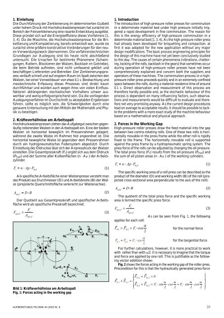
2. Kräfteverhältnisse am <strong>Arbeitsspalt</strong><br />
<strong>Hochdruck</strong>walzenpressen ziehen das Aufgabegut zwischen gegenläufig<br />
rotierenden Walzen in den <strong>Arbeitsspalt</strong> ein. Eine der beiden<br />
Walzen ist horizontal beweglich <strong>im</strong> Pressenrahmen gelagert,<br />
während die zweite Walze <strong>im</strong> Rahmen fest angeordnet ist. Die<br />
horizontal bewegliche Walze ist gegenüber dem Pressenrahmen<br />
durch ein hydropneumatisches Federsystem abgestützt. Durch<br />
Einstellung des Öldruckes lässt sich der Anpressdruck der Walzen<br />
einstellen. Die Gesamtpresskraft (F t ) ergibt sich aus dem Öldruck<br />
(P hyd ) und der Summe aller Kolbenflächen (n · A P ) der Arbeitszylinder.<br />
F t<br />
Als spezifische Arbeitsfläche einer Walzenpresse versteht man<br />
das Produkt aus Durchmesser (D) und Arbeitsbreite (B) der Walze<br />
(projizierte Querschnittsfläche senkrecht zur Walzenachse).<br />
F<br />
= n · Ap · P<br />
specf<br />
Ft<br />
=<br />
A<br />
specf<br />
hyd<br />
A<br />
(2)<br />
spcf<br />
= D · B<br />
Der Quotient aus Gesamtpresskraft und spezifischer Arbeitsfläche<br />
wird als spezifische Presskraft bezeichnet.<br />
(1)<br />
(3)<br />
1. Introduction<br />
The introduction of high-pressure roller presses for comminution<br />
in a determinate material bed under high pressure initially triggered<br />
a rapid development in fine comminution. The reason for<br />
this is the energy efficiency of high-pressure comminution in a<br />
determinate material bed [1, 3, 4]. As the high-pressure roller press<br />
had already been developed for briquetting and compaction, at<br />
first it was adopted for the new application without any major<br />
design modifications. The basic process engineering principles for<br />
the design of this machine have not yet been conclusively studied<br />
to this day. The causes of certain phenomena (vibrations, chattering,<br />
locking of the rolls, backlash in the gears) that somet<strong>im</strong>es occur<br />
during operation of high-pressure roller presses have not been<br />
comprehensively explained and concern both the suppliers and<br />
operators of these machines. The comminution process in a highpressure<br />
roller press proceeds quickly and in an extremely confined<br />
space between the rolls, during a material residence t<strong>im</strong>e of around<br />
0.1 s. Direct observation and measurement of this process are<br />
therefore hardly possible and, as the stochastic behaviour of this<br />
process is dependent on many influencing factors, such observations<br />
and measurements would be difficult to evaluate and therefore<br />
not very promising anyway. As the current design procedures<br />
lead on average to acceptable results, it should be possible to tackle<br />
the problems with a more exact study of the machine behaviour<br />
based on a mathematical and physical approach.<br />
2. Forces in the Working Gap<br />
High-pressure roller presses draw the feed material into the gap<br />
between two contra-rotating rolls. One of these two rolls is horizontally<br />
movable in the press frame while the other roll is rigidly<br />
fixed to the frame. The horizontally movable roll is supported<br />
against the press frame by a hydropneumatic spring system. The<br />
press force of the rolls can be adjusted by changing the oil pressure.<br />
The total press force (F t ) results from the oil pressure (P hyd ) and<br />
the sum of all piston areas (n · A P ) of the working cylinders.<br />
F t<br />
The specific working area of a roll press can be described as the<br />
product of the diameter (D) and working width (B) of the roll (projected<br />
cross-sectional area perpendicular to the axis of the roll):<br />
A<br />
= n · Ap · P<br />
spcf<br />
=<br />
D · B<br />
hyd<br />
The quotient of the total press force and the specific working<br />
area is termed the specific press force.<br />
Ft<br />
Fspecf<br />
=<br />
(3)<br />
Aspecf<br />
As can be seen from Fig. 1, the following<br />
applies for each roll:<br />
FN1 = FN2<br />
= Ft·<br />
⋅cos α<br />
for the normal force<br />
2<br />
(1)<br />
(2)<br />
for the tangential force<br />
For further calculations, however, it is more practical to work<br />
with rather than with /2. It is necessary to <strong>im</strong>agine that the torque<br />
and force are applied by one roll. This is justifiable as the following<br />
vector addition shows:<br />
Fig. 2 shows the forces acting in the working gap of the roller press.<br />
Precondition for this is that the hydraulically generated press force<br />
Bild 1: Kräfteverhältnisse am <strong>Arbeitsspalt</strong><br />
Fig. 1: Forces acting in the working gap<br />
F<br />
⎧FNx1 + FNx2<br />
= 0<br />
⎪<br />
+ FN<br />
= ⎨<br />
<br />
⎪FNy1 + FNx2<br />
= Ft ⋅sin ⋅ cos + Ft<br />
⋅sin ⋅cos<br />
⎩<br />
2 2 2 2<br />
N1 2<br />
⎫<br />
⎪<br />
⎬<br />
⎪<br />
⎭<br />
AUFBEREITUNGS TECHNIK 44 (2003) Nr. 8 23