Kraftverteilung im Arbeitsspalt von Hochdruck ... - Bauverlag
Kraftverteilung im Arbeitsspalt von Hochdruck ... - Bauverlag
Kraftverteilung im Arbeitsspalt von Hochdruck ... - Bauverlag

Erfolgreiche ePaper selbst erstellen
Machen Sie aus Ihren PDF Publikationen ein blätterbares Flipbook mit unserer einzigartigen Google optimierten e-Paper Software.
ergibt und für max der Winkel zwischen 1 und 2° liegt. Damit ist<br />
das Verhältnis B/C fix.<br />
Normiert man die Gleichung (10) mit dem Wert für die bei max<br />
auftretenden Kraft (Max<strong>im</strong>alkraft), erhält man folgende Gleichung:<br />
1<br />
B -C<br />
FN = e<br />
(12)<br />
B -B<br />
* *· *·<br />
max · e<br />
Für das Drehmoment muss gelten (Walzendurchmesser =1m):<br />
T ∫ F <br />
·<br />
*<br />
d<br />
<br />
= ( )<br />
(13)<br />
Das best<strong>im</strong>mte Integral der Gleichung (10) in den Grenzen <strong>von</strong><br />
0 bis strebt einem Grenzwert zu. Dieser Grenzwert stellt das<br />
2<br />
d<strong>im</strong>ensionslose Drehmoment des mit Aufgabegut gefüllten Zwischenraumes<br />
zwischen den Walzen dar. Das best<strong>im</strong>mte Integral in<br />
den Grenzen <strong>von</strong> 0 bis der normierten Gleichung (12) ist aber<br />
2<br />
auch der µ- Faktor. Er kann als das d<strong>im</strong>ensionslose Drehmoment<br />
aufgefasst werden, mit dem die Presskraft zu multiplizieren ist, um<br />
das zugehörige Drehmoment (Walzendurchmesser = 1 m) zu<br />
erhalten.<br />
Beispiel: Aus der Betriebserfahrung oder aus Versuchen wurde<br />
der µ-Faktor einer Teilfertigmahlung mit 0,095 best<strong>im</strong>mt. Da B<br />
aus mathematischen Überlegungen zwischen 0 und 1 liegen muss,<br />
ergibt sich<br />
<br />
2<br />
für =∫F<br />
( ) ⋅ d<br />
= 0 ,<br />
N<br />
095 und für (14)<br />
0<br />
F 1<br />
(15)<br />
e<br />
-047 , -21,<br />
15<br />
N( )= * * e<br />
-<br />
0 022 047 , 047 , · ·<br />
, *·<br />
In Bild 5 und 6 sind die Funktionen dargestellt, sowohl allgemein<br />
gültig d<strong>im</strong>ensionslos als auch für einen angenommenen Betriebsfall<br />
Walzenpresse mit 1 m 2 spezifischer Arbeitsfläche und<br />
6.000 kN/m 2 spezifischer Presskraft.<br />
6. Erkenntnisse aus den bisherigen Überlegungen<br />
• Der µ-Faktor, wie er bei der D<strong>im</strong>ensionierung <strong>von</strong> <strong>Hochdruck</strong>walzenpressen<br />
für die Zerkleinerung verwendet wird, ist das<br />
best<strong>im</strong>mte Integral der normierten Kraft als Funktion des<br />
Angriffswinkels F N() in den Grenzen <strong>von</strong> 0 bis . Das bedeutet,<br />
dass der µ-Faktor abn<strong>im</strong>mt, wenn z. B. durch Verringerung<br />
2<br />
der Beschickung der Füllungsgrad des Raumes zwischen den<br />
Walzen verringert wird oder wenn der beginnende Einzug des<br />
Aufgabegutes bei einem kleineren Winkel stattfindet.<br />
• Jeder Betreiber kennt das Problem, dass während des Anfahrens<br />
und Abfahrens die Schwankungen des Drehmomentes zunehmen<br />
und oft unzulässige Werte erreicht werden. Die Stammfunktion<br />
(das unbest<strong>im</strong>mte<br />
Integral) der Funktion F N()<br />
ändert ihren Wert <strong>im</strong> Bereich<br />
des voll gefüllten Zwischenraumes<br />
zwischen den<br />
Walzen bei einer Füllungsgradänderung<br />
nur geringfügig.<br />
Wird dieser jedoch klein<br />
gehalten, rufen schon geringe<br />
Änderungen der Aufgabegutmenge<br />
große Änderungen<br />
des µ-Faktors (des Drehmomentes)<br />
hervor. Der Grund<br />
hierfür ist der Verlauf der<br />
Kennlinie (Bild 7 und 8).<br />
7. Das Auftreten negativer<br />
Drehmomente<br />
Das Auftreten <strong>von</strong> Schwingungen<br />
des Drehmomentes mit<br />
The problem comes down to the determination of the constants<br />
A, B and C. From this function it is known that the extreme value<br />
(max<strong>im</strong>um) is calculated as<br />
max<br />
=- B (11)<br />
C<br />
For, it is known that the angle lies between 1 and 2°. The ratio<br />
B/C is then fixed.<br />
If function (10) is normalized with the value for the force (max<strong>im</strong>um<br />
force) generated at (max<strong>im</strong>um force), the following equation<br />
is obtained.<br />
F<br />
1<br />
B<br />
e<br />
* *· *·<br />
max · e<br />
N<br />
=<br />
B -B<br />
(12)<br />
The equation for the torque (with a roll diameter = 1 m) must be:<br />
T ∫F *· d<br />
= ( )<br />
(13)<br />
The definite integral of function (10) within the l<strong>im</strong>its from 0 to<br />
<br />
approaches a l<strong>im</strong>it value. This l<strong>im</strong>it value represents the d<strong>im</strong>ensionless<br />
torque of the space between the rolls (with a diameter of<br />
2<br />
1 m) filled with feed material. The determined integral within the<br />
l<strong>im</strong>its from 0 to of the normalized function (12) is, however, also<br />
2<br />
the µ factor. It can be explained as the d<strong>im</strong>ensionless torque with<br />
which the press force must be multiplied to obtain the associated<br />
torque (roll diameter = 1 m).<br />
Example: From practical experience or operating trials, the µ<br />
factor of a semi-finish grinding process has been calculated as<br />
0.095. As, based on mathematical considerations, B must lie<br />
between 0 and 1, the following results<br />
<br />
2<br />
for =∫FN ( ) ⋅ d<br />
= 0,<br />
095 and for (14)<br />
0<br />
F 1<br />
(15)<br />
e<br />
-047 , -21,<br />
15<br />
N( )= *· *·<br />
e<br />
-<br />
0 022 047 , 047 ,<br />
, *·<br />
In Figs. 5 and 6, the functions are shown, firstly as d<strong>im</strong>ensionless<br />
and universally valid, and secondly for an assumed case involving<br />
a roller press with 1 m 2 specific working area and 6000 kN/m 2 specific<br />
press force.<br />
6. What Findings can be Derived from these<br />
Considerations<br />
• The µ factor used for d<strong>im</strong>ensioning high-pressure roller presses<br />
for comminution is the definite integral of the normalized force<br />
as a function of the angle of force application F N() within the<br />
l<strong>im</strong>its of 0 to 2<br />
-C<br />
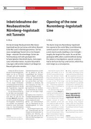
Bild 7: Krafteinleitung und Drehmomentverlauf (d<strong>im</strong>ensionslos)<br />
für den <strong>Arbeitsspalt</strong> <strong>von</strong> <strong>Hochdruck</strong>walzenpressen für einen mittleren<br />
µ-Faktor = 0,095<br />
Fig. 7: Power input and torque curve (d<strong>im</strong>ensionless) for the<br />
working gap of high-pressure roller presses for a mean µ factor =<br />
0.095<br />
. That means that the µ factor becomes lower when<br />
the material filling in the space<br />
between the rolls decreases, for<br />
example as a result of a lower<br />
feed rate, or when the feed<br />
material is drawn in at a smaller<br />
angle at the beginning.<br />
• Every operator is familiar<br />
with the problem of increased<br />
variation of the torque during<br />
machine start-up and shutdown,<br />
the torque then often<br />
exceeding the permissible<br />
values. If the space between<br />
the rolls is full or almost full,<br />
the value of the anti-derivative<br />
(the indefinite integral)<br />
of the function changes only<br />
slightly in response to a<br />
change in the filling degree. If<br />
the filling degree within the<br />
28 AUFBEREITUNGS TECHNIK 44 (2003) Nr. 8