Kraftverteilung im Arbeitsspalt von Hochdruck ... - Bauverlag
Kraftverteilung im Arbeitsspalt von Hochdruck ... - Bauverlag
Kraftverteilung im Arbeitsspalt von Hochdruck ... - Bauverlag

Sie wollen auch ein ePaper? Erhöhen Sie die Reichweite Ihrer Titel.
YUMPU macht aus Druck-PDFs automatisch weboptimierte ePaper, die Google liebt.
diesen Fall durch Addition der Vektoren der Teilkräfte F f tg= F f tg1 +<br />
F f tg2 ergibt, kann F f tg2 = 0 werden, dann beträgt das Gegenmoment<br />
F f tg= F f tg1 = F t · sin .<br />
Dieses Gegenmoment dreht die Walzen rückwärts. Das erklärt,<br />
weshalb <strong>Hochdruck</strong>walzenpressen besonders bei An-und Abfahrprozessen<br />
oder bei gedrosselter Aufgabegutmenge zu Vibrationen<br />
(Schwingungen) neigen. Das Auftreten negativer Drehmomente<br />
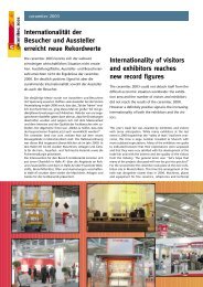
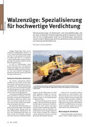
ist auch mit der <strong>Kraftverteilung</strong>sfunktion zu erklären. Bild 11 zeigt<br />
den Fall, dass die Schülpenbildung bei einem Winkel <strong>von</strong> 4°<br />
(0,07rad) aussetzt und der Spalt leer wird. Die Integration der<br />
<strong>Kraftverteilung</strong>sfunktion (F/F max ) erfolgt vom Punkt 4° auf der<br />
Abzisse und ergibt negative Werte für den Bereich < 4° und positive<br />
Werte für den Bereich > 4°.<br />
T = = ∫ F ( )⋅ d<br />
=0,<br />
020<br />
1<br />
T = = ∫ F ( )⋅ d<br />
= −0,<br />
075<br />
2<br />
<br />
2<br />
007 ,<br />
0<br />
007 ,<br />
N<br />
N<br />
Das Drehmoment T 2 ist das best<strong>im</strong>mte Integral <strong>von</strong> 0,07 (4°) bis<br />
0 und ist negativ. T 1 ist positiv. Das resultierende Drehmoment ist<br />
wegen /T 1 />/T 2 / negativ.<br />
T = T 1 +T 2<br />
Für das Beispiel beträgt T = –0,055 für F spcif = 6000kN/m 2 und<br />
D = 1m folgt:<br />
T = -330 kNm.<br />
rial is not constant or because the feed material contains single<br />
particles that are very much larger than the mean particle size, the<br />
point of force application “A” shifts towards larger angles of force<br />
application. That means that the force is applied as shown in Fig.<br />
8. This leads to a reversal of the torque direction and closing of<br />
the gap. As the applied force in this case results from the addition<br />
of the vectors of the force components F f tg= F f tg1 + F f tg2 can<br />
become equal to zero, and then the countertorque is F f tg= F f tg1=<br />
F t · sin .<br />
This countertorque causes the rolls to rotate backwards. That<br />
explains why high-pressure roller presses tend to suffer vibrations<br />
particularly during start-up or shutdown or with a choked feed rate.<br />
The occurrence of negative torques can also be explained with the<br />
force distribution function. Fig. 11 shows the case of flake formation<br />
stopping at an angle of 4° (0.07 rad) and the gap being emptied.<br />
The force distribution function (F/F max ) is integrated from<br />
point 4° on the x-axis and results in negative values for the range<br />
< 4° and positive values for the range > 4°.<br />
T = = ∫ F ( )⋅ d<br />
=0,<br />
020<br />
1<br />
T = = ∫ F ( )⋅ d<br />
= −0,<br />
075<br />
2<br />
<br />
2<br />
007 ,<br />
0<br />
007 ,<br />
N<br />
N<br />
The torque T 2 is the definite integral from 0.07 (4°) to 0 and is negative.<br />
T 1 is positive. The resulting torque is negative on account of<br />
/T 1 />/T 2 /.<br />
T = T 1 +T 2<br />
For the example, T = –0.055, for F spcif = 6000 kN/m 2 and D = 1 m<br />
it follows:<br />
Bild 11: Drehmomenterzeugung (Kurve INT (F/Fmax) bei nichtkontinuierlicher<br />
Beschickung und Abreissen der Schülpenbildung<br />
bei 4°<br />
Fig. 11: Generation of the torque (curve INT (F/Fmax) with intermittent<br />
feed and interruption of flake formation at 4°<br />
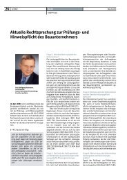
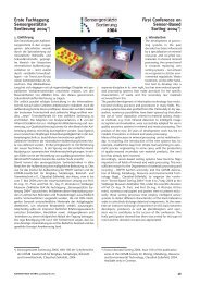
Lubjuhn [11] hat für die Funktion der Kraft in Abhängigkeit<br />
vom Drehwinkel gefunden, dass infolge <strong>von</strong> Rückdehnungen der<br />
Schülpe negative Drehwinkel möglich sind. Bild 12 zeigt einen<br />
angenommenen Verlauf der d<strong>im</strong>ensionslos gemachten Kraft als<br />
Funktion des Drehwinkels unter Beachtung <strong>von</strong> Rückdehnungen<br />
der Schülpe.<br />
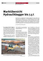
Bild 13 zeigt den zugehörigen Drehmomentverlauf. Auch hier<br />
besteht die Möglichkeit des Auftretens negativer Drehmomente,<br />
wenn der <strong>Arbeitsspalt</strong> nur gering gefüllt ist (sogenannter „verhungerter“<br />
Spalt). Die Gefahr, dass negative Drehmomente be<strong>im</strong><br />
„Verhungern“ des Spaltes auftreten, wird um so wahrscheinlicher,<br />
je größer der Wert der Rückdehnung ist. Im dargestellten Fall tritt<br />
ein Blockieren der Walzen bei einer Füllung des <strong>Arbeitsspalt</strong>es<br />
Bild 12: <strong>Kraftverteilung</strong> für den Fall des Auftretens <strong>von</strong> Schülpenexpansion<br />
(Rückdehnung: Funktion beginnt bei negativen Winkeln.)<br />
Fig. 12: Force distribution when flake expansion occurs (elastic<br />
relaxation: function begins at negative angles)<br />
T = -330 kNm.<br />
For the function of the force dependent on the angle of rotation,<br />
Lubjuhn [11] has found that the elastic relaxation of the flakes can<br />
lead to negative angles of rotation. Fig. 12 shows an assumed curve<br />
of the d<strong>im</strong>ensionless force as a function of the angle of rotation<br />
with allowance for the elastic relaxation of the flakes.<br />
Fig. 13 shows the associated torque curve. Here too, negative<br />
torques may result if the gap is only filled with a small quantity<br />
of material (“starved” gap). The danger of the occurrence of<br />
negative torques during starving of the gap becomes all the<br />
30 AUFBEREITUNGS TECHNIK 44 (2003) Nr. 8