Kraftverteilung im Arbeitsspalt von Hochdruck ... - Bauverlag
Kraftverteilung im Arbeitsspalt von Hochdruck ... - Bauverlag
Kraftverteilung im Arbeitsspalt von Hochdruck ... - Bauverlag

Sie wollen auch ein ePaper? Erhöhen Sie die Reichweite Ihrer Titel.
YUMPU macht aus Druck-PDFs automatisch weboptimierte ePaper, die Google liebt.
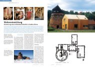
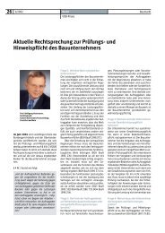
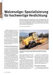
Bild 14: Drehmomenterzeugung bei diskontinuierlicher Beschickung<br />
in Abhängigkeit vom Winkel des Abreißpunktes der<br />
Schülpenbildung.<br />
Fig. 14: Generation of the torque with intermittent feed as a function<br />
of the angle of the point of interruption in flake formation<br />
ment ab (fallender Trend) und erst dann treten Schwingungen mit<br />
Backlash auf. Dabei zeigen die Walzen kurzzeitige Stillstände in der<br />
Drehbewegung und bei schweren Vibrationen ein kurzes Rückwärtsdrehen<br />
an. Ein Rückwärtsdrehen – hervorgerufen durch Torsionsspannungen<br />
des Antriebes – kann nur erfolgen, wenn die<br />
Kupplung wegen Überlast auslöst. Das führt aber zu keinen<br />
Schwingungen.<br />
Einen anderen Fall <strong>von</strong> Schwingungen beschreibt Schmitz [10].<br />
Dieser Fall tritt bei der Feinmahlung auf. Nach eigenen Beobachtungen<br />
verläuft die Entwicklung der Schwingung in diesem Fall<br />
wie folgt:<br />
Mit feiner werdendem Aufgabegut, z. B. bei der Teilfertigmahlung<br />
durch Steigerung der Sichterdrehzahl, wird der µ-Faktor<br />
zunächst größer und die Dicke sowie die Dichte der Schülpe<br />
(Spalt) nehmen zu. Kann die Schülpe der erhöhten Belastung nicht<br />
mehr standhalten, z. B. durch Lufteinschlüsse oder weil sie zu dick<br />
geworden ist, dann ist <strong>im</strong> Bereich des engsten Abstandes der Walzen<br />
(Punkt B, Bild 1) keine Gegenkraft zur Auflagekraft F A vorhanden,<br />
und die Drehrichtung der Walze wechselt in die Gegenrichtung.<br />
Es kommt zum Kraftstoß und die Schwingung wird ausgelöst.<br />
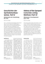
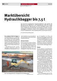
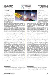
Bild 15 zeigt den Karftverlauf <strong>im</strong> <strong>Arbeitsspalt</strong> und den<br />
zugehörigen Drehmomentverlauf für unterschiedliche Abreißpunkte<br />
der Schülpenbildung. Für Abreißwinkel >3° gibt es kein<br />
positives Drehmoment.<br />
8. Schlussfolgerungen<br />
Für das Verhindern der oben beschriebenen negativen Betriebszustände<br />
<strong>von</strong> <strong>Hochdruck</strong>walzenpressen ergeben sich Forderungen<br />
an die Betriebsweise und die Ausrüstung <strong>von</strong> Anlagen zur Zerkleinerung,<br />
die mit <strong>Hochdruck</strong>walzenpressen arbeiten.<br />
Die Beschickung der <strong>Hochdruck</strong>walzenpresse muss regelbar<br />
sein. Einerseits muss stets soviel Gut zugeführt werden, wie der<br />
Walzenspalt zu jedem Zeitpunkt entsprechend der zeitlich veränderlichen<br />
Einzugsbedingungen benötigt, und andererseits müssen<br />
die Einzugsbedingungen beeinflusst werden können. Das gilt<br />
besonders für An- und Abfahrprozesse und für Betriebszustände,<br />
die zu sehr dicken und dichten Schülpen bei feinkörnigem Aufgabegut<br />
führen. Die Veränderung der Walzendrehzahl kann nur<br />
den Durchsatz beeinflussen. Die elektrische Leistungsaufnahme<br />
verändert sich dann proportional zum Durchsatz. Das Drehmoment<br />
wird dabei nicht verändert und somit besteht auch kein Einfluss<br />
auf die Einzugsbedingungen. Regelungskonzepte, die <strong>von</strong><br />
einer Drehzahlbeeinflussung ausgehen, können keinen Erfolg<br />
haben. Größte Bedeutung kommt der Wahl der spezifischen Presskraft<br />
zu, da sie einen Einfluss auf den Kraftangriffswinkel, das<br />
Drehmoment und die max<strong>im</strong>ale Presskraft <strong>im</strong> Spalt hat. Durch die<br />
Wahl der spezifischen Arbeitsfläche der Walzen wird durch den<br />
Bild 15: Drehmomenterzeugung bei nichtkontinuierlicher Beschickung<br />
und Abreißen der Schülpenbildung (Parameter: Winkel<br />
des Abreißpunktes)<br />
Fig. 15: Generation of the torque with intermittent feed and interruption<br />
in flake formation (parameter: angle of the point of interruption)<br />
torque decreases (falling trend) and only then do vibrations with<br />
backlash occur. The rolls temporarily stop rotating and, if the<br />
vibrations are very strong, they may even rotate backwards for a<br />
short t<strong>im</strong>e. A reversed rotation can only be caused by torsional<br />
stresses of the drive if the clutch releases as a result of overload.<br />
This does not lead to any vibrations.<br />
Schmitz [10] describes another instance of vibrations. These are<br />
generated during fine grinding. According to the author’s own<br />
observations, in this case the vibrations develop as follows:<br />
With increasingly fine feed material, e.g. during semi-finish<br />
grinding based on a higher classifier speed, the µ factor initially<br />
becomes larger and the thickness of the flake (gap) increases; the<br />
density of the flake increases at the same t<strong>im</strong>e. If the flake is no<br />
longer able to withstand the increased load, e.g. owing to<br />
entrapped air or because it has become too thick, then in the region<br />
of the narrowest distance between the rolls (point B, Fig. 1) there<br />
is no force to counter the load pressure FA, and the direction of<br />
roll rotation reverses. This results in an <strong>im</strong>pact force and a vibration<br />
is excited. Fig. 15 shows the pattern of force in the working gap<br />
and the associated torque curve for different points of interruption<br />
in flake information. For interruption angles >3°, there is no positive<br />
torque.<br />
8. Conclusions<br />
To prevent the negative operating states of high-pressure roller<br />
presses described above, the operation and equipment of comminution<br />
plants incorporating high-pressure roller presses must<br />
meet certain requirements.<br />
The feed to the high-pressure roller press must be controllable.<br />
On the one hand, as much material must always be supplied to the<br />
gap as this requires at each point in t<strong>im</strong>e depending on the changing<br />
material draw-in conditions. On the other hand, it must be possible<br />
to influence the material draw-in conditions. This applies particularly<br />
to the start-up and shutdown phases as well as operating<br />
modes that lead to very thick and dense flakes when the press is<br />
handling fine-grained feed material. Changing the speed of the<br />
rolls can only influence the throughput rate. The electric power<br />
consumption then changes proportionally to the throughput rate.<br />
The torque is not changed in this process and therefore the conditions<br />
of the draw-in the feed material are not influenced. Control<br />
concepts based on influencing operation by adjustment of the<br />
speed of the rolls cannot be successful therefore.<br />
The selection of the specific press force is of the greatest <strong>im</strong>portance,<br />
as this influences the angle of force application, the torque<br />
and the max<strong>im</strong>um press force in the gap. By selection of the specific<br />
working surface of the roll, the suppliers also define the specific<br />
press force. Design errors here are paid for with machine<br />
32 AUFBEREITUNGS TECHNIK 44 (2003) Nr. 8