Kraftverteilung im Arbeitsspalt von Hochdruck ... - Bauverlag
Kraftverteilung im Arbeitsspalt von Hochdruck ... - Bauverlag
Kraftverteilung im Arbeitsspalt von Hochdruck ... - Bauverlag

Sie wollen auch ein ePaper? Erhöhen Sie die Reichweite Ihrer Titel.
YUMPU macht aus Druck-PDFs automatisch weboptimierte ePaper, die Google liebt.
Wie aus Bild 1 zu entnehmen ist, gilt für jede Walze:<br />
F F F<br />
N1 N2<br />
t<br />
2<br />
für die Normalkraft<br />
= = ⋅cos α F t on the line connecting the roll mid-points on the horizontally<br />
für die Tangentialkraft<br />
Für weitere Berechnungen ist es jedoch praktischer mit und nicht<br />
mit /2 zu rechnen. Man geht da<strong>von</strong> aus, dass Drehmoment und<br />
Kraft <strong>von</strong> einer Walze aufgebracht werden, wie folgende Vektoraddition<br />
zeigt:<br />
F<br />
⎧FNx1 + FNx2<br />
= 0<br />
⎫<br />
⎪<br />
⎪<br />
+ FN<br />
= ⎨<br />
⎬<br />
⎪FNy1 + FNx2<br />
= Ft ⋅sin ⋅ cos + Ft<br />
⋅sin ⋅cos<br />
⎪<br />
⎩<br />
2 2 2 2 ⎭<br />
N1 2<br />
⎧Ftgx1 + Ftgx2<br />
= 0<br />
⎫<br />
f<br />
⎪<br />
⎪<br />
+ Ftg<br />
= ⎨<br />
f<br />
f ⎬<br />
⎪Ftgy1 + Ftgy2<br />
= Ft ⋅sin ⋅ cos + Ft<br />
⋅sin ⋅cos<br />
⎪<br />
⎩<br />
2 2 2 2 ⎭<br />
f<br />
Ftg1 2<br />
f<br />
f<br />
FN1 + FN2<br />
= Ft·<br />
• sinα<br />
Ftg 1<br />
+ Ftg2<br />
= Ft<br />
·•<br />
sinα<br />
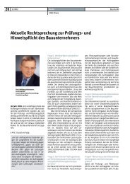
Bild 2 zeigt die Kräfteverhältnisse am <strong>Arbeitsspalt</strong> der Walzenpresse.<br />
Vorausgesetzt wird, dass die hydraulisch erzeugte Presskraft<br />
F t auf der Verbindungslinie der Walzenmittelpunkte an der<br />
horizontal beweglichen Walze in Richtung auf die Festwalze<br />
angreift. Die Übertragung der Presskraft auf das Mahlgut durch<br />
die sich drehenden Walzen erfolgt <strong>im</strong> <strong>Arbeitsspalt</strong> über die<br />
Berührungsfläche des Mahlgutes und der Walzenoberfläche. Das<br />
Mahlgut wird <strong>im</strong> <strong>Arbeitsspalt</strong> durch die horizontalen Kräfte (Bild 1)<br />
in x-Richtung F A und -F A wie bei einem Pressvorgang belastet.<br />
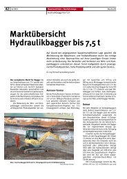
Gleichzeitig wirkt in y-Richtung die Einzugskraft F Z . Wie aus dem<br />
Schrifttum [11] bekannt, ist die horizontal wirkende Kraft eine<br />
Funktion <strong>von</strong> y (Bild 3) und eine Funktion der Längskoordinate<br />
z in Richtung der Walzenachse. Für die Betrachtungen in diesem<br />
Artikel soll eine zweid<strong>im</strong>ensionale Betrachtung (x-y Ebene) ausreichen<br />
(Mittelwert der Funktionen in z-Richtung)<br />
Die so genannte Grip Force (GF = F tg = sin · F t ) best<strong>im</strong>mt das<br />
Drehmoment. Die y-Komponente der Grip Force ist die Einzugskraft,<br />
die auf das Aufgabegut am Einzugspunkt A wirkt.<br />
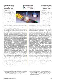
Bild 3: Kraft und Drehmoment (d<strong>im</strong>ensionslos) als Funktion des<br />
Berührungswinkels der Walzenoberfläche und des Mahlgutes<br />
Fig. 3: Force and torque (d<strong>im</strong>ensionless) as a function of the angle<br />
of contact of the roll surface and the product<br />
⎧Ftgx1 + Ftgx2<br />
= 0<br />
⎫<br />
f ⎪<br />
⎪<br />
+ Ftg<br />
= ⎨<br />
f<br />
f ⎬<br />
⎪Ftgy1 + Ftgy2<br />
= Ft ⋅sin ⋅ cos + Ft<br />
⋅sin ⋅cos<br />
⎪<br />
⎩<br />
2 2 2 2 ⎭<br />
f<br />
Ftg1 2<br />
F + F = F·<br />
• sinα<br />
N1 N2<br />
t<br />
F + F = F·<br />
• sinα<br />
tg1 tg2<br />
t<br />
f<br />
f<br />
movable roll is applied in the direction of the fixed roll. The press<br />
force on the product is transmitted by the rotating rolls in the gap,<br />
over the contact surface of the product and the roll surface. In the<br />
gap, the product stressed by the horizontal forces (Fig. 1) in the x-<br />
direction, i.e. F A and – F A , as in a press cycle. At the same t<strong>im</strong>e,<br />
the draw-in force F Z acts in the y-direction. As known from the literature<br />
(11), the force acting in the horizontal is a function of y (see<br />
Fig. 3) and a function of the longitudinal coordinate z in the direction<br />
of the roll axis. For the observations in this paper, a twod<strong>im</strong>ensional<br />
analysis (x-y plane) should be sufficient (mean value<br />
of the functions in the z-direction).<br />
The grip force (GF = F tg = sin · F t ) determines the torque. The<br />
y component of the grip force is the draw-in force acting on the<br />
feed material at draw-in point A.<br />
Bild 2: Details der Kräfte am <strong>Arbeitsspalt</strong><br />
Fig. 2: Details of the forces in the working gap<br />
Bild 4: Scheinbarer Ort der Walze zur Zeit t = 2 für einen mit<br />
dem Mahlgut mitfahrenden Betrachter<br />
Fig. 4: Apparent location of the roll at the t<strong>im</strong>e t = 2 for a product<br />
with a travelling observer<br />
24 AUFBEREITUNGS TECHNIK 44 (2003) Nr. 8