Kraftverteilung im Arbeitsspalt von Hochdruck ... - Bauverlag
Kraftverteilung im Arbeitsspalt von Hochdruck ... - Bauverlag
Kraftverteilung im Arbeitsspalt von Hochdruck ... - Bauverlag

Sie wollen auch ein ePaper? Erhöhen Sie die Reichweite Ihrer Titel.
YUMPU macht aus Druck-PDFs automatisch weboptimierte ePaper, die Google liebt.
3. Berechnung der Leistungsaufnahme einer<br />
<strong>Hochdruck</strong>walzenpresse<br />
Die für die Zerkleinerungsarbeit benötigte Leistung des Antriebes<br />
einer <strong>Hochdruck</strong>walzenpresse berechnet sich wie folgt.<br />
Es gilt aber auch:<br />
P = T · (3)<br />
P = · F · (4)<br />
Das Drehmoment berechnet sich als Vektorprodukt<br />
aus (3) und (4) folgt: T f = F f x r oder T = F · r · sin (5)<br />
T · = · F · (6)<br />
da = r , ergibt sich : F · r · sin r = · F · <br />
und somit gilt: = sin (7)<br />
oder: = F · r · sin = T eff (8)<br />
F · r T max<br />
Die Gleichung (8) zeigt, dass der µ-Faktor das Verhältnis <strong>von</strong><br />
tatsächlich bei der Zerkleinerung in einer Gutbettwalzenpresse<br />
auftretendem zum max<strong>im</strong>al mit der Presskraft (µ =1) erzeugbaren<br />
Drehmoment ist. Der µ-Faktor hat eine ähnlich fundamentale<br />
Bedeutung wie der Wirkungsgrad.<br />
4. Best<strong>im</strong>mung des µ-Faktors<br />
Der µ-Faktor ist mit Gleichung (4) best<strong>im</strong>mbar:<br />
=<br />
F·<br />
P<br />
(9)<br />
Gleichung (9) stellt das Verhältnis der für ein best<strong>im</strong>mtes Mahlgut<br />
erzeugbaren Leistung zur max<strong>im</strong>al mit der Anpresskraft „F“<br />
möglich erzeugbaren Leistung dar.<br />
Mit Gleichung (9) ist die Best<strong>im</strong>mung des µ-Faktors kein Problem,<br />
da alle erforderlichen Größen messbar sind. Für ein Datenerfassungssystem<br />
(wie z. B. dem Data Logger vom Ing. Büro Hübler)<br />
besteht kein Problem, µ online als Trend mit hoher Messfrequenz<br />
darzustellen. Auf diese Weise können unter Betriebsbedingungen<br />
statistisch gesicherte Werte und funktionale Zusammenhänge zu<br />
anderen Größen ermittelt werden.<br />
5. Zusammenhänge mit dem µ-Faktor<br />
Nach Gleichung (7) ist der µ-Faktor gleich dem Sinus des Einzugswinkels.<br />
Wird der <strong>Hochdruck</strong>walzenpresse ofenfallender Klinker aufgegeben,<br />
ergibt sich µ zu etwa 0,08 und damit ein Einzugswinkel<br />
<strong>von</strong> 4,6°.<br />
Bei einem Walzendurchmesser <strong>von</strong> 1 m<br />
und einem <strong>Arbeitsspalt</strong> <strong>von</strong><br />
23 mm<br />
wird bei<br />
4,6° Einzugswinkel<br />
ein Korn <strong>von</strong> 23 mm + 1.000 mm·(1-cos 4,6) = 26,22 mm eingezogen.<br />
Es zeigt sich aber, dass selbst größere aus dem Ofen kommende<br />
Ansatzstücke mit Korngrößen >100 mm <strong>von</strong> Walzen mit 1 m<br />
Durchmesser problemlos erfasst werden. Für diesen Fall müsste<br />
der µ-Faktor bei 0,4 liegen.<br />
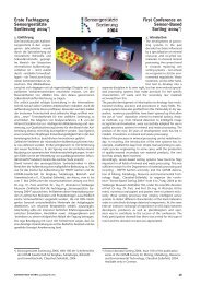
Trägt man die bei unterschiedlichen Presskräften erhaltenen µ-<br />
Faktoren als Funktion der Presskraft in ein doppelt logarithmisches<br />
Netz ein, ergibt sich eine Gerade.<br />
Bild 5 zeigt die Abhängigkeit des µ-Faktors <strong>von</strong> der spezifischen<br />
Presskraft (µ = F(F spcf )) für drei unterschiedliche Fälle. Die<br />
Bild 6 gibt die Verhältnisse beispielhaft für die Mahlung <strong>von</strong> Klinker<br />
wieder:<br />
Für das Drehmoment gilt:<br />
T F · A · und damit T A · F · F F<br />
=<br />
specf specf<br />
=<br />
specf specf<br />
= ( specf )<br />
* * sin * * ( )<br />
3. Calculation of the Power Consumption of a<br />
High-Pressure Roller Press<br />
The drive power of a high-pressure roller press for comminution<br />
is calculated as follows.<br />
The following also applies:<br />
P = T · (3)<br />
P = · F · (4)<br />
The torque is calculated as the vector product<br />
from (3) and (4), it follows:<br />
T f = F f x r or T = F · r · sin (5)<br />
T · = · F · (6)<br />
as = r , the following results : F · r · sin r = · F · <br />
and therefore the following applies: = sin (7)<br />
but it is also possible to write: = F · r · sin = T eff (8)<br />
F · r T max<br />
Equation (8) shows that the µ factor is the relationship of<br />
the actually effective torque during comminution in a high-pressure<br />
roller mill to the max<strong>im</strong>um torque that can be generated<br />
with the press force (µ =1). The µ factor has a s<strong>im</strong>ilarly fundamental<br />
significance as the efficiency. It is worth studying this<br />
closer.<br />
4. Determination of the µ Factor<br />
The µ factor can be determined with Equation (9):<br />
=<br />
F·<br />
P<br />
(9)<br />
Eq. (9) represents the relationship of the power that can be generated<br />
when a certain product is handled to the max<strong>im</strong>um power<br />
that can be generated with the press force “F”.<br />
The µ factor can be easily determined with Eq. (9) as the<br />
required variables can all be measured. A data acquisition system<br />
(e.g. the Data Logger from Ing. Büro Hübler) has no problem in<br />
displaying<br />
·<br />
µ online<br />
·<br />
as a trend with high measurement<br />
· ·<br />
frequency.<br />
Bild 5: Abhängigkeit des µ-Faktors <strong>von</strong> der spezifischen Presskraft<br />
für 3 unterschiedliche Materialien<br />
Fig. 5: Dependence of the µ factor on the specific press force for<br />
three different products<br />
26 AUFBEREITUNGS TECHNIK 44 (2003) Nr. 8