260381 - Dungs
260381 - Dungs
260381 - Dungs

Sie wollen auch ein ePaper? Erhöhen Sie die Reichweite Ihrer Titel.
YUMPU macht aus Druck-PDFs automatisch weboptimierte ePaper, die Google liebt.
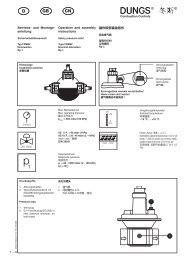
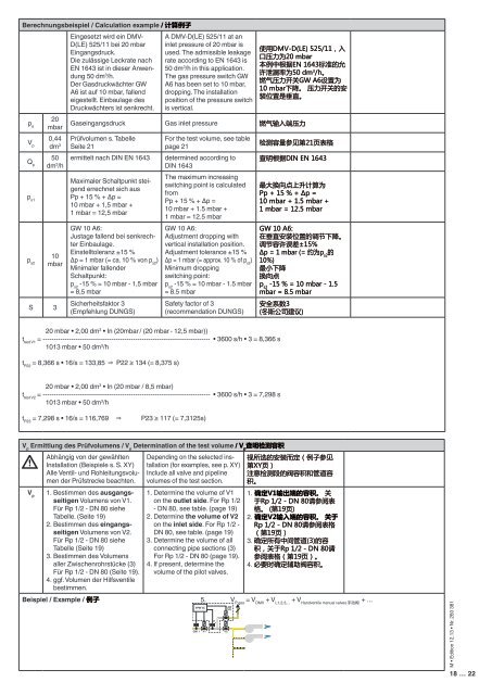
Berechnungsbeispiel / Calculation example / 计 算 例 子<br />
p e<br />
20<br />
mbar<br />
V p<br />
0,44<br />
dm 3<br />
Q p<br />
50<br />
dm 3 /h<br />
p s1<br />
p s2<br />
10<br />
mbar<br />
S 3<br />
Eingesetzt wird ein DMV-<br />
D(LE) 525/11 bei 20 mbar<br />
Eingangsdruck.<br />
Die zulässige Leckrate nach<br />
EN 1643 ist in dieser Anwendung<br />
50 dm 3 /h.<br />
Der Gasdruckwächter GW<br />
A6 ist auf 10 mbar, fallend<br />
eigestellt. Einbaulage des<br />
Druckwächters ist senkrecht.<br />
A DMV-D(LE) 525/11 at an<br />
inlet pressure of 20 mbar is<br />
used. The admissible leakage<br />
rate according to EN 1643 is<br />
50 dm 3 /h in this application.<br />
The gas pressure switch GW<br />
A6 has been set to 10 mbar,<br />
dropping. The installation<br />
position of the pressure switch<br />
is vertical.<br />
使 用 DMV-D(LE) 525/11, 入<br />
口 压 力 为 20 mbar<br />
本 例 中 根 据 EN 1643 标 准 的 允<br />
许 泄 漏 率 为 50 dm 3 /h。<br />
燃 气 压 力 开 关 GW A6 设 置 为<br />
10 mbar 下 降 。 压 力 开 关 的 安<br />
装 位 置 是 垂 直 。<br />
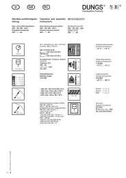
Gaseingangsdruck Gas inlet pressure 燃 气 输 入 端 压 力<br />
Prüfvolumen s. Tabelle<br />
Seite 21<br />
ermittelt nach DIN EN 1643<br />
Maximaler Schaltpunkt steigend<br />
errechnet sich aus<br />
Pp + 15 % + Δp =<br />
10 mbar + 1,5 mbar +<br />
1 mbar = 12,5 mbar<br />
GW 10 A6:<br />
Justage fallend bei senkrechter<br />
Einbaulage.<br />
Einstelltoleranz ±15 %<br />
Δp = 1 mbar (= ca. 10 % von p s2<br />
)<br />
Minimaler fallender<br />
Schaltpunkt:<br />
p s2<br />
-15 % = 10 mbar - 1,5 mbar<br />
= 8,5 mbar<br />
Sicherheitsfaktor 3<br />
(Empfehlung DUNGS)<br />
For the test volume, see table<br />
page 21<br />
determined according to<br />
DIN 1643<br />
The maximum increasing<br />
switching point is calculated<br />
from<br />
Pp + 15 % + Δp =<br />
10 mbar + 1.5 mbar +<br />
1 mbar = 12.5 mbar<br />
GW 10 A6:<br />
Adjustment dropping with<br />
vertical installation position.<br />
Adjustment tolerance ±15 %<br />
Δp = 1 mbar (= approx. 10 % of p s2<br />
)<br />
Minimum dropping<br />
switching point:<br />
p s2<br />
-15 % = 10 mbar - 1.5 mbar<br />
= 8.5 mbar<br />
Safety factor of 3<br />
(recommendation DUNGS)<br />
检 测 容 量 参 见 第 21 页 表 格<br />
查 明 根 据 DIN EN 1643<br />
最 大 换 向 点 上 升 计 算 为<br />
Pp + 15 % + Δp =<br />
10 mbar + 1.5 mbar +<br />
1 mbar = 12.5 mbar<br />
GW 10 A6:<br />
在 垂 直 安 装 位 置 的 调 节 下 降 。<br />
调 节 容 许 误 差 ±15%<br />
Δp = 1 mbar (= 约 为 p s2<br />
的<br />
10%)<br />
最 小 下 降<br />
换 向 点<br />
p s2<br />
-15 % = 10 mbar - 1.5<br />
mbar = 8.5 mbar<br />
安 全 系 数 3<br />
( 冬 斯 公 司 建 议 )<br />
20 mbar • 2,00 dm 3 • In (20mbar / (20 mbar - 12,5 mbar))<br />
t test V1<br />
= ---------------------------------------------------------------------------- • 3600 s/h • 3 = 8,366 s<br />
1013 mbar • 50 dm 3 /h<br />
t P22<br />
= 8,366 s • 16/s = 133,85 ⇒ P22 ≥ 134 (= 8,375 s)<br />
20 mbar • 2,00 dm 3 • In (20 mbar / 8,5 mbar)<br />
t test V2<br />
= ---------------------------------------------------------------------------- • 3600 s/h • 3 = 7,298 s<br />
1013 mbar • 50 dm 3 /h<br />
t P23<br />
= 7,298 s • 16/s = 116,769 ⇒ P23 ≥ 117 (= 7,3125s)<br />
V p<br />
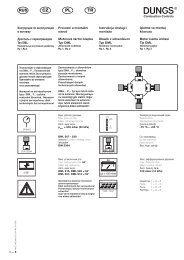
Ermittlung des Prüfvolumens / V p<br />
Determination of the test volume / V p<br />
查 明 检 测 容 积<br />
V p<br />
Abhängig von der gewählten<br />
Installation (Beispiele s. S. XY)<br />
Alle Ventil- und Rohleitungsvolumen<br />
der Prüfstrecke beachten.<br />
1. Bestimmen des ausgangsseitigen<br />
Volumens von V1.<br />
Für Rp 1/2 - DN 80 siehe<br />
Tabelle. (Seite 19)<br />
2. Bestimmen des eingangsseitigen<br />
Volumens von V2.<br />
Für Rp 1/2 - DN 80 siehe<br />
Tabelle (Seite 19)<br />
3. Bestimmen des Volumens<br />
aller Zwischenrohrstücke (3)<br />
Für Rp 1/2 - DN 80 (Seite 19).<br />
4. ggf. Volumen der Hilfsventile<br />
bestimmen.<br />
Depending on the selected installation<br />
(for examples, see p. XY)<br />
Include all valve and pipeline<br />
volumes of the test section.<br />
1. Determine the volume of V1<br />
on the outlet side. For Rp 1/2<br />
- DN 80, see table. (page 19)<br />
2. Determine the volume of V2<br />
on the inlet side. For Rp 1/2 -<br />
DN 80, see table. (page 19)<br />
3. Determine the volume of all<br />
connecting pipe sections (3)<br />
For Rp 1/2 - DN 80 (page 19).<br />
4. If present, determine the<br />
volume of the pilot valves.<br />
视 所 选 的 安 装 而 定 ( 例 子 参 见<br />
第 XY 页 )<br />
注 意 检 测 段 的 阀 容 积 和 管 道 容<br />
积 。<br />
1. 确 定 V1 输 出 端 的 容 积 。 关<br />
于 Rp 1/2 - DN 80 请 参 阅 表<br />
格 。 ( 第 19 页 )<br />
2. 确 定 V2 输 入 端 的 容 积 。 关 于<br />
Rp 1/2 - DN 80 请 参 阅 表 格<br />
( 第 19 页 )<br />
3. 确 定 所 有 中 间 管 道 (3) 的 容<br />
积 , 关 于 Rp 1/2 - DN 80 请<br />
参 阅 表 格 ( 第 19 页 )。<br />
4. 必 要 时 确 定 辅 助 阀 容 积 。<br />
Beispiel / Example / 例 子 5. V P ges<br />
= V DMV<br />
+ V L1,2,3,...<br />
+ V Handventile manual valves 手 动 阀 + ...<br />
VPM VC<br />
GW 1<br />
V1<br />
P p<br />
V2<br />
LGV<br />
(NO)<br />
M • Edition 12.13 • Nr. 260 381<br />
18 … 22