

9-2015
Fachzeitschrift für Hochfrequenz- und Mikrowellentechnik
Fachzeitschrift für Hochfrequenz- und Mikrowellentechnik

Erfolgreiche ePaper selbst erstellen
Machen Sie aus Ihren PDF Publikationen ein blätterbares Flipbook mit unserer einzigartigen Google optimierten e-Paper Software.
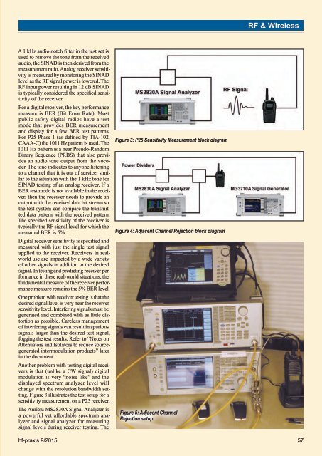
RF & WirelessA 1 kHz audio notch filter in the test set isused to remove the tone from the receivedaudio, the SINAD is then derived from themeasurement ratio. Analog receiver sensitivityis measured by monitoring the SINADlevel as the RF signal power is lowered. TheRF input power resulting in 12 dB SINADis typically considered the specified sensitivityof the receiver.For a digital receiver, the key performancemeasure is BER (Bit Error Rate). Mostpublic safety digital radios have a testmode that provides BER measurementand display for a few BER test patterns.For P25 Phase 1 (as defined by TIA-102.CAAA-C) the 1011 Hz pattern is used. The1011 Hz pattern is a near Pseudo-RandomBinary Sequence (PRBS) that also providesan audio tone output from the vocoder.The tone indicates to anyone listeningto a channel that it is out of service, similarto the situation with the 1 kHz tone forSINAD testing of an analog receiver. If aBER test mode is not available in the receiver,then the receiver needs to provide anoutput with the received data bit stream sothe test system can compare the transmitteddata pattern with the received pattern.The specified sensitivity of the receiver istypically the RF signal level for which themeasured BER is 5%.Digital receiver sensitivity is specified andmeasured with just the single test signalapplied to the receiver. Receivers in realworlduse are impacted by a wide varietyof other signals in addition to the desiredsignal. In testing and predicting receiver performancein these real-world situations, thefundamental measure of the receiver performancemeasure remains the 5% BER level.One problem with receiver testing is that thedesired signal level is very near the receiversensitivity level. Interfering signals must begenerated and combined with as little distortionas possible. Careless managementof interfering signals can result in spurioussignals larger than the desired test signal,fogging the test results. Refer to “Notes onAttenuators and Isolators to reduce sourcegeneratedintermodulation products” laterin the document.Another problem with testing digital receiversis that (unlike a CW signal) digitalmodulation is very “noise like” and thedisplayed spectrum analyzer level willchange with the resolution bandwidth setting.Figure 3 illustrates the test setup for asensitivity measurement on a P25 receiver.The Anritsu MS2830A Signal Analyzer isa powerful yet affordable spectrum analyzerand signal analyzer for measuringsignal levels during receiver testing. TheFigure 3: P25 Sensitivity Measurement block diagramFigure 4: Adjacent Channel Rejection block diagramFigure 5: Adjacent ChannelRejection setuphf-praxis 9/<strong>2015</strong> 57


