

9-2015
Fachzeitschrift für Hochfrequenz- und Mikrowellentechnik
Fachzeitschrift für Hochfrequenz- und Mikrowellentechnik

Sie wollen auch ein ePaper? Erhöhen Sie die Reichweite Ihrer Titel.
YUMPU macht aus Druck-PDFs automatisch weboptimierte ePaper, die Google liebt.
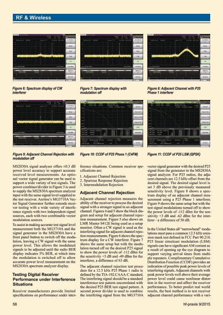
RF & WirelessFigure 6: Spectrum display of CWinterfererFigure 7: Spectrum display withmodulation offFigure 8: Adjacent Channel with P25Phase 1 interfererFigure 9: Adjacent Channel Rejection withmodulation offMS2830A signal analyzer offers ±0.3 dBpower level accuracy to support accuratereceived level measurements. An optionalvector signal generator can be used tosupport a wide variety of test signals. Thepower combiner/divider in Figure 3 is usedto supply the MS2830A spectrum analyzerinput with the same signal level supplied tothe test receiver. Anritsu’s MG3710A VectorSignal Generator further extends receivertesting with a wide variety of interferencesignals with two independent signalsources, each with two combinable vectormodulation sources.To assist in making accurate test signal levelmeasurement both the MG3710A and thesignal generator in the MS2830A have afront panel button to switch off the modulation,leaving a CW signal with the samepower level. This allows the modulatedsignals to be adjusted until the radio BERdisplay indicates 5% BER, at which timethe modulation is switched off to allowaccurate power level measurement on theMS2830A spectrum analyzer display.Testing Digital ReceiverPerformance under InterferenceSituationsFigure 10: CCDF of P25 Phase 1 (C4FM)Receiver manufacturers provide limitedspecifications on performance under interferencesituations. Common receiver specificationsare:1. Adjacent Channel Rejection2. Spurious Response Rejection3. Intermodulation RejectionAdjacent Channel RejectionAdjacent channel rejection measures theability of the receiver to process the desiredsignal with a stronger signal in an adjacentchannel. Figures 4 and 5 show the block diagramand setup for adjacent channel rejectionmeasurement. Figure 5 also shows anLMR Master S412E being used as a setupmonitor. Often a CW signal is used as theinterfering signal for adjacent channel rejectionmeasurements. Figure 6 shows the spectrumdisplay for a CW interferer. Figure 7shows the same setup but with the modulationturned off on the desired P25 signalto show the power levels of -112 dBm forthe sensitivity +3 dB and -49 dBm for theinterferer, a difference of 63 dB.The adjacent channel rejection test procedurefor a 12.5 kHz P25 Phase 1 radio isdefined by the TIA-102.CAAA-C standard.The interfering signal should be a standardinterference test pattern uncorrelated withthe desired P25 BER test signal pattern. Asecond power divider is used to combinethe interfering signal from the MG3710AFigure 11: CCDF of P25 LSM (QPSK)vector signal generator with the desired P25signal from the generator in the MS2830Asignal analyzer. For P25 radios, the adjacentchannels are 12.5 kHz offset from thedesired signal. The desired signal level isset 3 dB above the previously measuredsensitivity level. Figure 8 shows a spectrumdisplay of an adjacent channel measurementusing a P25 Phase 1 interferer.Figure 9 shows the same setup but with thetest signal modulations turned off to showthe power levels of -112 dBm for the sensitivity+3 dB and -62 dBm for the interferer- a difference of 50 dB.In the United States all “narrowband” modulationsmust pass a common 12.5 kHz emissionmask test defined in FCC Part 90.210.P25 linear simulcast modulation (LSM)signals can have significant AM content asa result of opening up the eye diagram tosupport varying arrival times from multiplerepeaters. Complimentary CumulativeDistribution Function (CCDF) provides anindication of possible peak power levels ofinterfering signals. Adjacent channels withpeak power levels well above their averagepower level could cause nonlinear distortionin the receiver and affect the receiverperformance. To better predict real worldresults, the best method is to test receiveradjacent channel performance with a vari-58 hf-praxis 9/<strong>2015</strong>


