

9-2015
Fachzeitschrift für Hochfrequenz- und Mikrowellentechnik
Fachzeitschrift für Hochfrequenz- und Mikrowellentechnik

Sie wollen auch ein ePaper? Erhöhen Sie die Reichweite Ihrer Titel.
YUMPU macht aus Druck-PDFs automatisch weboptimierte ePaper, die Google liebt.
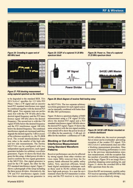
RF & WirelessFigure 24: Crowding in upper end of800 MHz bandFigure 25: CCDF of a captured 31.25 MHzspectrum blockFigure 26: Power vs. Time of a captured31.25 MHz spectrum blockFigure 27: P25 blocking measurementusing captured spectrum as the interfererto be degraded to the standard BER. TIA-102.CAAA-C specifies for 12.5 kHz P25Phase 1 that a CW signal and an uncorrelatedP25 standard interference test signalbe combined together with the desired P25BER signal. Two separate tests are performed;first with the CW 50 kHz above thedesired signal frequency and the P25 interferencesignal 100 kHz above the desiredfrequency. The second test is with the CWsignal 50 kHz below the desired frequencyand the P25 interference signal 100 kHzbelow the desired frequency. The combinedinterference signals are increased until theydegrade the desired signal by 3 dB in excessof the reference sensitivity i.e., the 5% BERlevel. The overall intermodulation distortionvalue is the smaller of the high sideand low side measurements. The AnritsuMG3710A can be configured with twoindependent signal generators; each signalgenerator includes two arbitrary waveformgenerators. Figure 16 shows the block diagramfor this setup. A third power divider isused to combine the two signal generatorsin the MG3710A. One signal generator isused for the CW signal, the other for theP25 standard interference signal. Figure 17shows a photograph of the setup includingthe three power dividers. Alternatively, theCW and P25 interference signals couldhave been created using one generator inFigure 28: Block diagram of receiver field testing setupthe MG3710A. The two separate arbitrarywaveform generators for each signal sourcecan be internally combined with better than80 dBc IM3 performance.Figure 18 shows a spectrum display of IMDmeasurement using a CW signal 50 kHzabove the desired P25 signal and a P25standard interference signal 100 kHz abovethe desired P25 signal. Figure 19 shows thesame setup but with the test signal modulationsturned off to show the power levels of-112 dBm for the sensitivity +3 dB and -41dBm for the interferer - a difference of 71 dB.Blocking or Out-of-BandInterference MeasurementUsing Standard WaveformPatternsReceiver performance can also be affectedby strong signals from other wireless servicesmany MHz removed from the frequencybands allocated for public safetyradios. New, spectrum efficient, broadbanddigital modulation techniques suchas those used in 3G/4G cellular data canhave high peak powers. In a near-far environmentwhere the P25 transmitter is milesaway and the P25 receiver is very near aFigure 29: S412E LMR Master mounted ona vehicle dashboard3G/4G cellular site, the receiver preamplifieror mixer can be overloaded - preventingreception of the weaker P25 signal. TIA-102.CAAA-C unfortunately does not offera blocking measurement procedure. Measurementof blocking performance is similarto the previous intermodulation rejectionmeasurement, with the exception thatthe number of possible interfering signalscan be large. Figure 20 is an image from asuburban shopping center parking lot, andFigure 21 shows the crowded 850 to 900MHz spectrum from the site.Given this RF environment, a public safetyP25 receiver operating at 860.050 MHz maynot receive even a relatively stronghf-praxis 9/<strong>2015</strong> 61


