

10-2020
Fachzeitschrift für Hochfrequenz- und Mikrowellentechnik
Fachzeitschrift für Hochfrequenz- und Mikrowellentechnik

Sie wollen auch ein ePaper? Erhöhen Sie die Reichweite Ihrer Titel.
YUMPU macht aus Druck-PDFs automatisch weboptimierte ePaper, die Google liebt.
APPLICATION SPOTLIGHT<br />
RFIC/SiP Design: AWR AXIEM EM with Virtuoso RF<br />
The AWR AXIEM EM simulator is now integrated with the Cadence Virtuoso RF solution, providing designers with an<br />
integrated circuit (IC), package/module design flow that improves productivity by eliminating the design failures caused<br />
by the manual translation of data. A single golden schematic is used for simulation, layout versus schematic (LVS), and<br />
EM analysis and verification, without the need for unique schematics for EM and LVS.<br />
Using the AWR AXIEM Simulator with Virtuoso RF<br />
The AWR AXIEM EM simulator within AWR Microwave Office ® circuit design software is a best-in-class planar, open<br />
boundary 3D planar engine that solves for currents on horizontal metal traces and vertical vias. Prior to the Virtuoso<br />
integration of the AWR AXIEM EM solver, users of both tools relied upon manual integration, namely exporting and<br />
importing the layout between the Virtuoso environment and the AWR AXIEM simulator within the AWR Microwave Office<br />
environment.<br />
Integrated AWR AXIEM Solver/Virtuoso RF Flow<br />
The integrated AWR AXIEM EM solver within the Cadence IC/ system-in-package (SiP) flow for layout of silicon ICs<br />
provides design optimization and layout verification within a single schematic.<br />
Traditionally, layout and schematic are loosely coupled in Cadence software. The golden schematic couples much more<br />
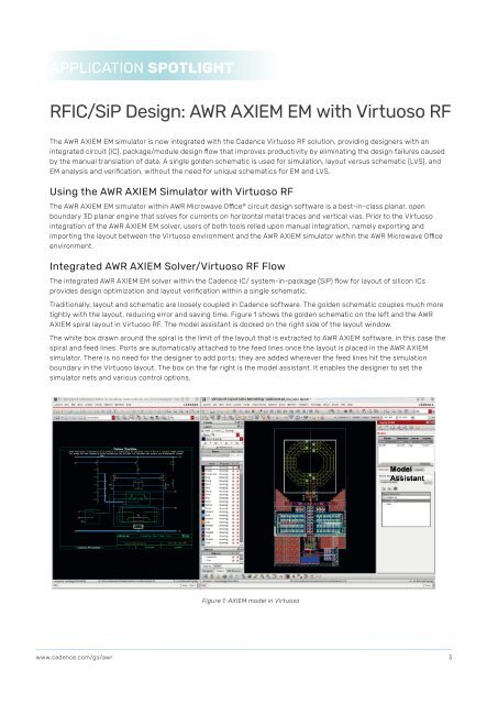
tightly with the layout, reducing error and saving time. Figure 1 shows the golden schematic on the left and the AWR<br />
AXIEM spiral layout in Virtuoso RF. The model assistant is docked on the right side of the layout window.<br />
The white box drawn around the spiral is the limit of the layout that is extracted to AWR AXIEM software, in this case the<br />
spiral and feed lines. Ports are automatically attached to the feed lines once the layout is placed in the AWR AXIEM<br />
simulator. There is no need for the designer to add ports; they are added wherever the feed lines hit the simulation<br />
boundary in the Virtuoso layout. The box on the far right is the model assistant. It enables the designer to set the<br />
simulator nets and various control options.<br />
Figure 1: AXIEM model in Virtuoso<br />
www.cadence.com/go/awr<br />
3


