

Practical Ship Hydrodynamics
Practical Ship Hydrodynamics
Practical Ship Hydrodynamics

You also want an ePaper? Increase the reach of your titles
YUMPU automatically turns print PDFs into web optimized ePapers that Google loves.
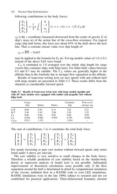
162 <strong>Practical</strong> <strong>Ship</strong> <strong>Hydrodynamics</strong><br />
following contributions to the body forces:<br />
⎧ ⎫ ⎧ ⎫<br />
⎪⎨<br />
X4 ⎪⎬ � ⎪⎨<br />
0 ⎪⎬<br />
Y4 1 1<br />
D<br />
⎪⎩ K4 ⎪⎭ 2 L ⎪⎩ zD ⎪⎭<br />
x<br />
⊲v C x Ð r⊳jv C x Ð rjTxCD dx<br />
N4<br />
zD is the z coordinate (measured downward from the centre of gravity G of<br />
ship’s mass m) of the action line of the cross-flow resistance. For typical<br />
cargo ship hull forms, this force acts about 65% of the draft above the keel<br />
line. Thus a constant (mean) value over ship length of:<br />
zD D KG 0.65T<br />
may be applied to the formula for X4 etc. For tug models values of 1.0 š 0.1<br />
instead of the above 0.65 were found.<br />
CD is estimated as 1.0 averaged over the whole ship length for cargo<br />
vessels like container ships with bilge keels. For fuller hulls values between<br />
0.5 and 0.7 may be suitable. The CD values are generally higher in the<br />
aftbody than in the forebody due to stronger flow separation in the aftbody.<br />
Results of transverse towing tests (at zero speed) with and without heel<br />
with large models are presented in Table 5.3. These results differ from the<br />
situation at considerable forward speed.<br />
Table 5.3 Results of transverse towin tests with large models upright and<br />
with 10 ◦ heel; models were equipped with rudder and propeller but without<br />
bilge keels<br />
Cargo Container Twin-screw<br />
ship Tanker Tanker ship salvage tug<br />
L/B 6.66 5.83 6.11 7.61 5.21<br />
B/T 2.46 2.43 2.96 2.93 2.25<br />
CB 0.66 0.84 0.81 0.58 0.58<br />
CD 0.562 0.983 0.594 0.791 0.826<br />
CD10° 0.511 1.151 – 1.014 –<br />
The sum of contributions 1 to 4 constitutes the total body force:<br />
⎧ ⎫<br />
⎪⎨<br />
X ⎪⎬<br />
Y<br />
⎪⎩ K ⎪⎭<br />
N<br />
D<br />
⎧ ⎫<br />
⎪⎨<br />
X1 ⎪⎬<br />
Y1<br />
⎪⎩ K1 ⎪⎭ C<br />
⎧ ⎫<br />
⎪⎨<br />
X2 ⎪⎬<br />
Y2<br />
⎪⎩ K2 ⎪⎭ C<br />
⎧ ⎫<br />
⎪⎨<br />
X3 ⎪⎬<br />
Y3<br />
⎪⎩ K3 ⎪⎭ C<br />
⎧ ⎫<br />
⎪⎨<br />
X4 ⎪⎬<br />
Y4<br />
⎪⎩ K4 ⎪⎭<br />
N1<br />
N2<br />
N3<br />
For steady traversing or pure yaw motion without forward speed, only terms<br />
listed under 4 above are relevant.<br />
The yaw stability is very sensitive to small changes in the body forces.<br />
Therefore a reliable prediction of yaw stability based on the slender-body<br />
theory or regression analysis of model tests is not possible. Substantial<br />
improvements of theoretical calculations seem possible only if the flow<br />
separation around the hull is determined in detail by computational simulation<br />
of the viscous, turbulent flow in a RANSE code or even LES simulations.<br />
RANSE simulations were in the late 1990s subject to research and not yet<br />
established for practical applications. Three-dimensional boundary element<br />
N4


