CSE-Semaphore TWinSoft Manual - ioSelect
CSE-Semaphore TWinSoft Manual - ioSelect
CSE-Semaphore TWinSoft Manual - ioSelect

Create successful ePaper yourself
Turn your PDF publications into a flip-book with our unique Google optimized e-Paper software.
10. Programs<br />
10.1. Ladder – Principle<br />
Introduction<br />
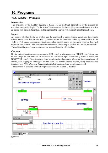
The principle of the Ladder diagram is based on an electrical description of the process or<br />
machine, using relay logic. To the left of the screen are the inputs (they are conditions for which<br />
an action will be undertaken) and to the right are the outputs (which result from these actions).<br />
Inputs<br />
All inputs, whether digital or analog, can be combined to create logical equations (two inputs<br />
follow on the same line for an , and one above the other and linked by a vertical bar for an<br />
). All analog comparison functions and/or digital inputs on the same program line will<br />
represent true or false. The result defines the actions of the output (will or will not be performed).<br />
The different types of Input conditions are accessible in the LD Toolbar.<br />
Outputs<br />
Digital output functions are engagements (SET relay) or disengagement (RESET relay), they can<br />
be the image or the opposite of the result of the tested input conditions (OUTPUT relay and<br />
NEGATIVE relay). Other functions have been introduced proper to telemetry like transmission of<br />
alarms, data logging or sending of DTMF tone. To process analog outputs, many mathematical<br />
functions and POU (Program Organization Units) functions have been implemented.<br />
The selection of different types of outputs is accessible in the LD Toolbar.<br />
figure 18<br />
<strong>TWinSoft</strong>: 8.32 – Getting Started 24