Power Modular Concept PMC 40
Power Modular Concept PMC 40
Power Modular Concept PMC 40

You also want an ePaper? Increase the reach of your titles
YUMPU automatically turns print PDFs into web optimized ePapers that Google loves.
Installation<br />
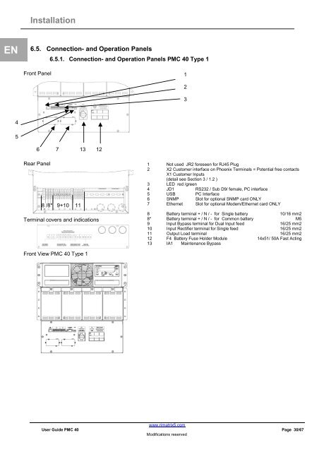
EN 6.5. Connection- and Operation Panels<br />
6.5.1. Connection- and Operation Panels <strong>PMC</strong> <strong>40</strong> Type 1<br />
4<br />
5<br />
Front Panel<br />
6 7 13 12<br />
Rear Panel<br />
8 /8* 9+10 11<br />
Terminal covers and indications<br />
Front View <strong>PMC</strong> <strong>40</strong> Type 1<br />
1 Not used JR2 foreseen for RJ45 Plug<br />
2 X2 Customer interface on Phoenix Terminals = Potential free contacts<br />
X1 Customer Inputs<br />
(detail see Section 3 / 1.2 )<br />
3 LED red /green<br />
4 JD1 RS232 / Sub D9/ female, PC interface<br />
5 USB PC Interface<br />
6 SNMP Slot for optional SNMP card ONLY<br />
7 Ethernet Slot for optional Modem/Ethernet card ONLY<br />
8 Battery terminal + / N / - for Single battery 10/16 mm2<br />
8* Battery terminal + / N / - for Common battery M5<br />
9 Input Bypass terminal for Dual Input feed 16/25 mm2<br />
10 Input Rectifier terminal for Single feed 16/25 mm2<br />
11 Output Load terminal 16/25 mm2<br />
12 F4 Battery Fuse Holder Module 14x51/ 50A Fast Acting<br />
13 IA1 Maintenance Bypass<br />
www.rimatrix5.com<br />
User Guide <strong>PMC</strong> <strong>40</strong> Page 30/67<br />
Modifications reserved<br />
1<br />
2<br />
3