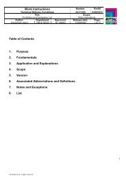
Power Modular Concept PMC 40
Power Modular Concept PMC 40
Power Modular Concept PMC 40

Create successful ePaper yourself
Turn your PDF publications into a flip-book with our unique Google optimized e-Paper software.
EN<br />
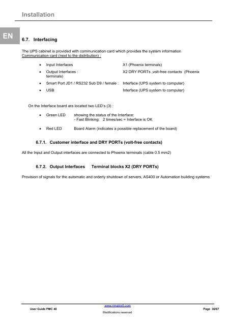
Installation<br />
6.7. Interfacing<br />
The UPS cabinet is provided with communication card which provides the system information<br />
Communication card (next to the distribution) :<br />
• Input Interfaces X1 (Phoenix terminals)<br />
• Output Interfaces : X2 DRY PORTs ,volt-free contacts (Phoenix<br />
terminals)<br />
• Smart Port JD1 / RS232 Sub D9 / female : Interface (UPS system to computer)<br />
• USB Interface (UPS system to computer)<br />
On the Interface board are located two LED’s (3) :<br />
• Green LED showing the status of the Interface:<br />
- Fast Blinking: 2 times/sec = Interface is OK<br />
• Red LED Board Alarm (indicates a possible replacement of the board)<br />
6.7.1. Customer interface and DRY PORTs (volt-free contacts)<br />
All the Input and Output interfaces are connected to Phoenix terminals (cable 0.5 mm2)<br />
6.7.2. Output Interfaces Terminal blocks X2 (DRY PORTs)<br />
Provision of signals for the automatic and orderly shutdown of servers, AS<strong>40</strong>0 or Automation building systems<br />
www.rimatrix5.com<br />
User Guide <strong>PMC</strong> <strong>40</strong> Page 36/67<br />
Modifications reserved