Power Modular Concept PMC 40
Power Modular Concept PMC 40
Power Modular Concept PMC 40

You also want an ePaper? Increase the reach of your titles
YUMPU automatically turns print PDFs into web optimized ePapers that Google loves.
EN<br />
Operation<br />
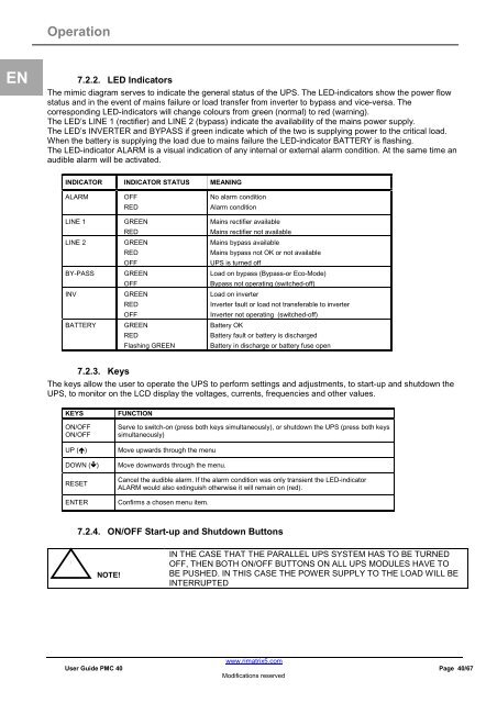
7.2.2. LED Indicators<br />
The mimic diagram serves to indicate the general status of the UPS. The LED-indicators show the power flow<br />
status and in the event of mains failure or load transfer from inverter to bypass and vice-versa. The<br />
corresponding LED-indicators will change colours from green (normal) to red (warning).<br />
The LED’s LINE 1 (rectifier) and LINE 2 (bypass) indicate the availability of the mains power supply.<br />
The LED’s INVERTER and BYPASS if green indicate which of the two is supplying power to the critical load.<br />
When the battery is supplying the load due to mains failure the LED-indicator BATTERY is flashing.<br />
The LED-indicator ALARM is a visual indication of any internal or external alarm condition. At the same time an<br />
audible alarm will be activated.<br />
INDICATOR INDICATOR STATUS MEANING<br />
ALARM OFF<br />
RED<br />
LINE 1 GREEN<br />
RED<br />
LINE 2 GREEN<br />
RED<br />
OFF<br />
BY-PASS GREEN<br />
OFF<br />
INV GREEN<br />
RED<br />
OFF<br />
BATTERY GREEN<br />
7.2.3. Keys<br />
RED<br />
Flashing GREEN<br />
No alarm condition<br />
Alarm condition<br />
Mains rectifier available<br />
Mains rectifier not available<br />
Mains bypass available<br />
Mains bypass not OK or not available<br />
UPS is turned off<br />
Load on bypass (Bypass-or Eco-Mode)<br />
Bypass not operating (switched-off)<br />
Load on inverter<br />
Inverter fault or load not transferable to inverter<br />
Inverter not operating (switched-off)<br />
Battery OK<br />
Battery fault or battery is discharged<br />
Battery in discharge or battery fuse open<br />
The keys allow the user to operate the UPS to perform settings and adjustments, to start-up and shutdown the<br />
UPS, to monitor on the LCD display the voltages, currents, frequencies and other values.<br />
KEYS FUNCTION<br />
ON/OFF<br />
ON/OFF<br />
Serve to switch-on (press both keys simultaneously), or shutdown the UPS (press both keys<br />
simultaneously)<br />
UP () Move upwards through the menu<br />
DOWN () Move downwards through the menu.<br />
RESET<br />
Cancel the audible alarm. If the alarm condition was only transient the LED-indicator<br />
ALARM would also extinguish otherwise it will remain on (red).<br />
ENTER Confirms a chosen menu item.<br />
!<br />
7.2.4. ON/OFF Start-up and Shutdown Buttons<br />
NOTE!<br />
IN THE CASE THAT THE PARALLEL UPS SYSTEM HAS TO BE TURNED<br />
OFF, THEN BOTH ON/OFF BUTTONS ON ALL UPS MODULES HAVE TO<br />
BE PUSHED. IN THIS CASE THE POWER SUPPLY TO THE LOAD WILL BE<br />
INTERRUPTED<br />
www.rimatrix5.com<br />
User Guide <strong>PMC</strong> <strong>40</strong> Page <strong>40</strong>/67<br />
Modifications reserved