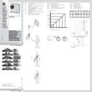
Power Modular Concept PMC 40
Power Modular Concept PMC 40
Power Modular Concept PMC 40

Create successful ePaper yourself
Turn your PDF publications into a flip-book with our unique Google optimized e-Paper software.
EN<br />
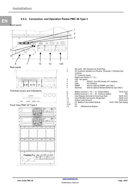
Installation<br />
Front panel<br />
4<br />
5<br />
Rear panel<br />
6.5.3. Connection- and Operation Panels <strong>PMC</strong> <strong>40</strong> Type 3<br />
6 7 13 12 12A<br />
8 /8* 9+10 11<br />
Terminal covers and indications<br />
Front View <strong>PMC</strong> <strong>40</strong> Type 3<br />
1 Not used JR2 foreseen for RJ45 Plug<br />
2 X2 Customer interface on Phoenix Terminals = Potential free<br />
contacts<br />
X1 Customer Inputs<br />
(detail see Section 3 / 1.2 )<br />
3 LED red /green<br />
4 JD1 RS232 / Sub D9/ female, PC interface<br />
5 USB PC Interface<br />
6 SNMP Slot for optional SNMP card ONLY<br />
7 Ethernet Slot for optional Modem/Ethernet card ONLY<br />
8 Battery terminal + / N / - for Single battery 10/16 mm2<br />
8* Battery terminal + / N / - for Common battery M5<br />
9 Input Bypass terminal for Dual Input feed 16/25 mm2<br />
10 Input Rectifier terminal for Single feed 16/25 mm2<br />
11 Output Load terminal 16/25 mm2<br />
12 F4 Battery Fuse Holder Module 14x51/ 50A Fast Acting<br />
12.A F5<br />
13 IA1 Maintenance Bypass<br />
www.rimatrix5.com<br />
User Guide <strong>PMC</strong> <strong>40</strong> Page 32/67<br />
Modifications reserved<br />
1<br />
2<br />
3