

Chapter 19 Universal Asynchronous Receiver-Transmitter (UART).pdf
Chapter 19 Universal Asynchronous Receiver-Transmitter (UART).pdf
Chapter 19 Universal Asynchronous Receiver-Transmitter (UART).pdf

Create successful ePaper yourself
Turn your PDF publications into a flip-book with our unique Google optimized e-Paper software.
Functional Description www.ti.com<br />
determines DMA mode 0 to mode 3 based on the supplementary control register (<strong>UART</strong>_SCR)<br />
description.<br />
For example:<br />
• If no DMA operation is desired, set the DMA_MODE_CTL bit to 1 and the DMA_MODE_2 bit field to<br />
0x0. (The DMA_MODE bit is discarded.)<br />
• If DMA mode 1 is desired, set the DMA_MODE_CTL bit to 0 and the DMA_MODE bit to 1, or set the<br />
DMA_MODE_CTL bit to 1 and the DMA_MODE_2 bit field to 01. (The DMA_MODE bit is discarded.)<br />
If the FIFOs are disabled (the <strong>UART</strong>i.<strong>UART</strong>_FCR[0] FIFO_EN bit is set to 0), the DMA occurs in singlecharacter<br />
transfers.<br />
When DMA mode 0 is programmed, the signals associated with DMA operation are not active.<br />
Depending on <strong>UART</strong>_MDR3[2] SET_DMA_TX_THRESHOLD, the threshold can be programmed different<br />
ways:<br />
• SET_TX_DMA_THRESHOLD = 1:<br />
The threshold value will be the value of the <strong>UART</strong>_TX_DMA_THRESHOLD register. If<br />
SET_TX_DMA_THRESHOLD + TX trigger spaces 64, then the default method of threshold is used:<br />
threshold value = TX FIFO size.<br />
• SET_TX_DMA_THRESHOLD = 0:<br />
The threshold value = TX FIFO size TX trigger space. The TX DMA line is asserted if the TX FIFO<br />
level is lower then the threshold. It remains asserted until TX trigger spaces number of bytes are<br />
written into the FIFO. The DMA line is then deasserted and the FIFO level is compared with the<br />
threshold value.<br />
<strong>19</strong>.3.6.4.1 DMA Transfers (DMA Mode 1, 2, or 3)<br />
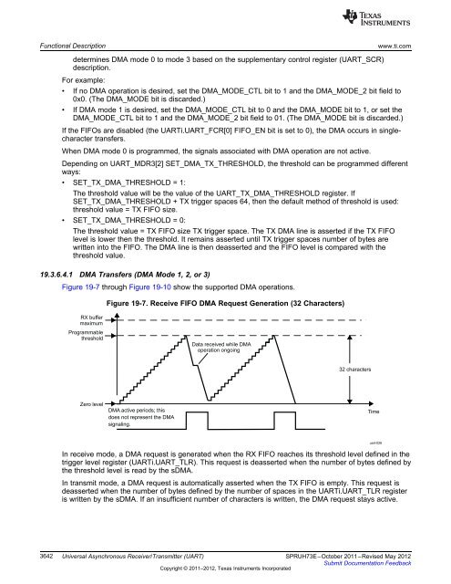
Figure <strong>19</strong>-7 through Figure <strong>19</strong>-10 show the supported DMA operations.<br />
RX buffer<br />
maximum<br />
Programmable<br />
threshold<br />
Zero level<br />
Figure <strong>19</strong>-7. Receive FIFO DMA Request Generation (32 Characters)<br />
DMA active periods; this<br />
does not represent the DMA<br />
signaling.<br />
Data received while DMA<br />
operation ongoing<br />
32 characters<br />
In receive mode, a DMA request is generated when the RX FIFO reaches its threshold level defined in the<br />
trigger level register (<strong>UART</strong>i.<strong>UART</strong>_TLR). This request is deasserted when the number of bytes defined by<br />
the threshold level is read by the sDMA.<br />
In transmit mode, a DMA request is automatically asserted when the TX FIFO is empty. This request is<br />
deasserted when the number of bytes defined by the number of spaces in the <strong>UART</strong>i.<strong>UART</strong>_TLR register<br />
is written by the sDMA. If an insufficient number of characters is written, the DMA request stays active.<br />
3642 <strong>Universal</strong> <strong>Asynchronous</strong> <strong>Receiver</strong>/<strong>Transmitter</strong> (<strong>UART</strong>) SPRUH73E–October 2011–Revised May 2012<br />
Submit Documentation Feedback<br />
Copyright © 2011–2012, Texas Instruments Incorporated<br />
Time<br />
uart-026


