CL100 / CL300 Service Manual - Welch Allyn
CL100 / CL300 Service Manual - Welch Allyn
CL100 / CL300 Service Manual - Welch Allyn

You also want an ePaper? Increase the reach of your titles
YUMPU automatically turns print PDFs into web optimized ePapers that Google loves.
6. Remove the 4 screws from the power supply and pull the supply out of the front to remove.<br />
7. Installation is the reverse process with the wires located as follows:<br />
P1 on power supply to J5 on PCBA (part no. A4-10670) - red wire<br />
P2A - Used to configure to 230v operation only - NOT USED<br />
P2 on power supply to J4 on PCBA (part no. A4-10670) - brown wire<br />
P3 on power supply to J1 on PCBA (part no. A4-10670) - blue wire<br />
P4 on power supply - black wire from red/black pair - housed in tubing<br />
P5 on power supply - red wire from red/black pair - housed in tubing<br />
P11 on power supply - red or white wire from red/black pair (thin wire pair)<br />
P12 on power supply - black wire from red/black pair (thin wire pair)<br />
PCBA (PART NO. A4-10670) REMOVAL<br />
1. Remove power as noted above.<br />
2. Not the location and remove connectors from J6, J7, J9, J10, J11, and J12.<br />
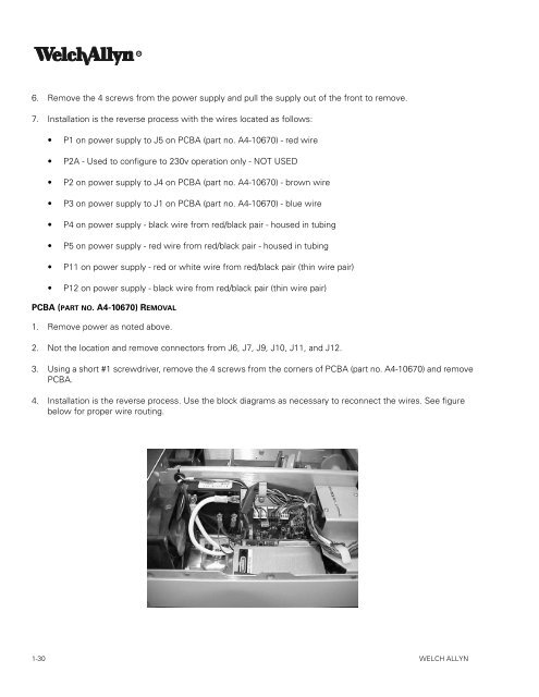
3. Using a short #1 screwdriver, remove the 4 screws from the corners of PCBA (part no. A4-10670) and remove<br />
PCBA.<br />
4. Installation is the reverse process. Use the block diagrams as necessary to reconnect the wires. See figure<br />
below for proper wire routing.<br />
1-30 WELCH ALLYN