CL100 / CL300 Service Manual - Welch Allyn
CL100 / CL300 Service Manual - Welch Allyn
CL100 / CL300 Service Manual - Welch Allyn

You also want an ePaper? Increase the reach of your titles
YUMPU automatically turns print PDFs into web optimized ePapers that Google loves.
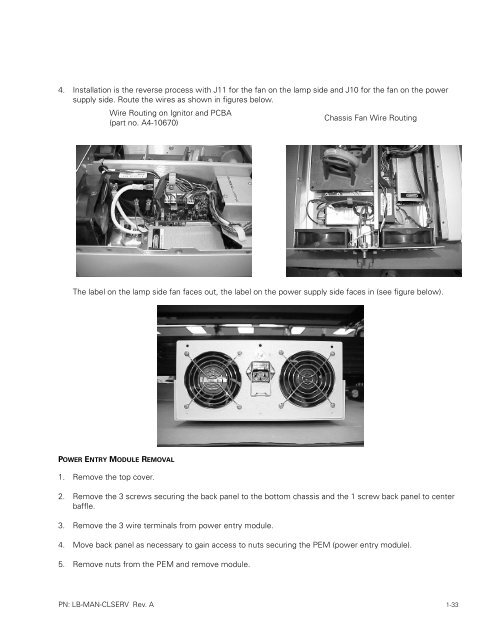
4. Installation is the reverse process with J11 for the fan on the lamp side and J10 for the fan on the power<br />
supply side. Route the wires as shown in figures below.<br />
Wire Routing on Ignitor and PCBA<br />
(part no. A4-10670)<br />
Chassis Fan Wire Routing<br />
The label on the lamp side fan faces out, the label on the power supply side faces in (see figure below).<br />
POWER ENTRY MODULE REMOVAL<br />
1. Remove the top cover.<br />
2. Remove the 3 screws securing the back panel to the bottom chassis and the 1 screw back panel to center<br />
baffle.<br />
3. Remove the 3 wire terminals from power entry module.<br />
4. Move back panel as necessary to gain access to nuts securing the PEM (power entry module).<br />
5. Remove nuts from the PEM and remove module.<br />
PN: LB-MAN-CLSERV Rev. A 1-33