CL100 / CL300 Service Manual - Welch Allyn
CL100 / CL300 Service Manual - Welch Allyn
CL100 / CL300 Service Manual - Welch Allyn

You also want an ePaper? Increase the reach of your titles
YUMPU automatically turns print PDFs into web optimized ePapers that Google loves.
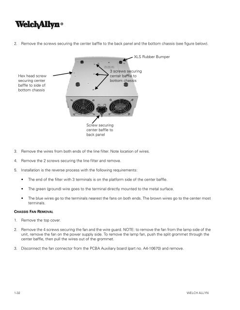
2. Remove the screws securing the center baffle to the back panel and the bottom chassis (see figure below).<br />
Hex head screw<br />
securing center<br />
baffle to side of<br />
bottom chassis<br />
3. Remove the wires from both ends of the line filter. Note location of wires.<br />
4. Remove the 2 screws securing the line filter and remove.<br />
5. Installation is the reverse process with the following requirements:<br />
The end of the filter with 3 terminals is on the platform side of the center baffle.<br />
The green (ground) wire goes to the terminal directly mounted to the metal surface.<br />
The blue wires go to the terminals nearest the fans on both ends. The brown wires go to the center most<br />
terminals.<br />
CHASSIS FAN REMOVAL<br />
1. Remove the top cover.<br />
Screw securing<br />
center baffle to<br />
back panel<br />
3 screws securing<br />
center baffle to<br />
bottom chassis<br />
XLS Rubber Bumper<br />
2. Remove the 4 screws securing the fan and the wire guard. NOTE: to remove the fan from the lamp side of the<br />
unit, remove the fan on the power supply side. To remove the lamp fan, push the split grommet through the<br />
center baffle, then pull the wires out of the grommet.<br />
3. Disconnect the fan connector from the PCBA Auxiliary board (part no. A4-10670) and remove.<br />
1-32 WELCH ALLYN