A Wavelength Converter Integrated with a Discretely Tunable Laser ...
A Wavelength Converter Integrated with a Discretely Tunable Laser ...
A Wavelength Converter Integrated with a Discretely Tunable Laser ...

Create successful ePaper yourself
Turn your PDF publications into a flip-book with our unique Google optimized e-Paper software.
2.2 Optical gating 11<br />
powers (in the fiber) that are required are between and dBm at 2.5 Gb/s and between<br />
and dBm at 10 Gb/s for the control power. The probe powers are lower, between<br />
¤ and dBm. The input power dynamic range for the control signal is typically 3 dB<br />
in dynamic operation. However, a 10 dB dynamic range, between dBm and dBm, for<br />
penalty free conversion at 5 Gb/s was reported in [22], using integrated pre-amplifiers. The<br />
wavelength span of a converter should, in principle, be such that the converter can convert to<br />
any of the WDM wavelengths of the network in which it is employed. A wavelength span<br />
of the converted output of 26-30 nm was reported in [16, 17, 26] and a span of even 80 nm<br />
(C-band and L-band) at 10 Gb/s in [19]. Optical signal to noise ratios (OSNR) of the converted<br />
output of 40-45 dB (0.1 nm resolution bandwidth) have been realized [14, 19] Apart from the<br />
noise, some of the control signal power exits from the converted output port of the converter,<br />
even in counter-propagating operation, due to reflections in the chip. The input signal rejection<br />
ratio (ISRR) is defined as the power difference between the converted output and the reflected<br />
control signal. The ISSR is typically 25-35 dB [14, 19].<br />
λprobe<br />
φ 1<br />
φ 2<br />
φ 1<br />
φ 2<br />
φ 1 −<br />
SOA<br />
φ 2<br />
time<br />
λconv<br />
Δτ<br />
delay<br />
λcontrol<br />
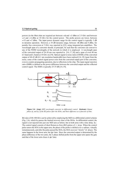
Figure 2.4: ((top)) MZI wavelength converter in differential control. (bottom)) Output<br />
phase and of the RZ pulses after the SOAs, and their difference as a function of time.<br />
Bit rates of 40-100 Gb/s can be achieved by employing the MZI in a differential control scheme<br />
(Fig. 2.4), which by-passes the limited recovery time of the SOAs. In differential control, the<br />
signal is not injected into just one MZI arm as before, but in both arms <strong>with</strong> a time delay .<br />
The control signal consists of short Return-to-Zero (RZ) pulses of £¤ ps. When the control<br />
pulse enters the SOA in the upper arm, the phase of the probe is shifted over radians, virtually<br />
instantaneously, and after the pulse passed the SOA, the SOA recovers ”slowly” (§¨ ps). The<br />
same happens in the lower arm, but later. Since the converted output is determined by the<br />
phase difference of the two arms, the phase shifted probe from the upper arm opens the gate<br />
and that of the lower arm closes it later.