A Wavelength Converter Integrated with a Discretely Tunable Laser ...
A Wavelength Converter Integrated with a Discretely Tunable Laser ...
A Wavelength Converter Integrated with a Discretely Tunable Laser ...

You also want an ePaper? Increase the reach of your titles
YUMPU automatically turns print PDFs into web optimized ePapers that Google loves.
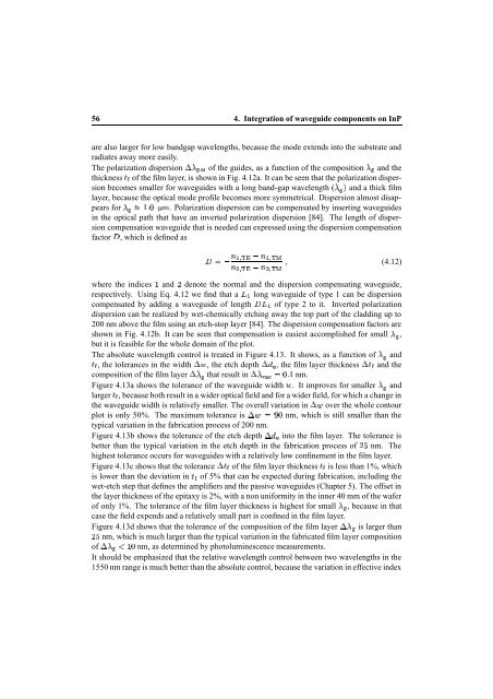
56 4. Integration of waveguide components on InP<br />
are also larger for low bandgap wavelengths, because the mode extends into the substrate and<br />
radiates away more easily.<br />
The polarization dispersion of the guides, as a function of the composition and the<br />
thickness of the film layer, is shown in Fig. 4.12a. It can be seen that the polarization dispersion<br />
becomes smaller for waveguides <strong>with</strong> a long band-gap wavelength and a thick film<br />
layer, because the optical mode profile becomes more symmetrical. Dispersion almost disappears<br />
for §©¤ . Polarization dispersion can be compensated by inserting waveguides<br />
in the optical path that have an inverted polarization dispersion [84]. The length of dispersion<br />
compensation waveguide that is needed can expressed using the dispersion compensation<br />
factor , which is defined as<br />
<br />
¦ ¦ <br />
<br />
where the ¤ indices and denote the normal and the dispersion compensating waveguide,<br />
respectively. Using Eq. 4.12 we find that a long waveguide of type 1 can be dispersion<br />
compensated by adding a waveguide of length of type 2 to it. Inverted polarization<br />
dispersion can be realized by wet-chemically etching away the top part of the cladding up to<br />
200 nm above the film using an etch-stop layer [84]. The dispersion compensation factors are<br />
shown in Fig. 4.12b. It can be seen that compensation is easiest accomplished for small ,<br />
but it is feasible for the whole domain of the plot.<br />
(4.12)<br />
The absolute wavelength control is treated in Figure 4.13. It shows, as a function of and<br />
, the tolerances in the width , the etch <br />
<br />
depth , the film layer <br />
<br />
thickness and the<br />
composition of the film layer that result ¤ in nm.<br />
Figure 4.13a shows the tolerance of the waveguide width . It improves for smaller and<br />
larger , because both result in a wider optical field and for a wider field, for which a change in<br />
the waveguide width is relatively smaller. The overall variation in over the whole contour<br />
plot is only 50%. The maximum tolerance is nm, which is still smaller than the<br />
typical variation in the fabrication process of 200 nm.<br />
Figure 4.13b shows the tolerance of the etch <br />
<br />
depth into the film layer. The tolerance is<br />
better than the typical variation in the etch depth in the fabrication process ¨ of nm. The<br />
highest tolerance occurs for waveguides <strong>with</strong> a relatively low confinement in the film layer.<br />
Figure 4.13c shows that the tolerance is less than 1%, which<br />
of the film layer thickness<br />
<br />
<br />
is lower than the deviation in of 5% that can be expected during fabrication, including the<br />
wet-etch step that defines the amplifiers and the passive waveguides (Chapter 5). The offset in<br />
the layer thickness of the epitaxy is 2%, <strong>with</strong> a non uniformity in the inner 40 mm of the wafer<br />
of only 1%. The tolerance of the film layer thickness is highest for small , because in that<br />
case the field expends and a relatively small part is confined in the film layer.<br />
Figure 4.13d shows that the tolerance of the composition of the film layer is larger than<br />
nm, which is much larger than the typical variation in the fabricated film layer composition<br />
¨<br />
£¥¤ of nm, as determined by photoluminescence measurements.<br />
It should be emphasized that the relative wavelength control between two wavelengths in the<br />
1550 nm range is much better than the absolute control, because the variation in effective index