A Wavelength Converter Integrated with a Discretely Tunable Laser ...
A Wavelength Converter Integrated with a Discretely Tunable Laser ...
A Wavelength Converter Integrated with a Discretely Tunable Laser ...

You also want an ePaper? Increase the reach of your titles
YUMPU automatically turns print PDFs into web optimized ePapers that Google loves.
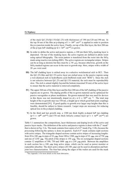
5.2 Epitaxy 65<br />
of the stack Q(1.25)/Q(1.55)/Q(1.25) <strong>with</strong> thicknesses of 190 nm/120 nm/190 nm. In<br />
the top 50 nm of the film an p-doping of ¤¤ cm is applied in order to position<br />
the p-n junction inside the active layer. Finally, on top of the film layer, the first 200 nm<br />
of the p-type InP cladding (p=¤ cm ) is grown.<br />
II) In order to define the active and passive regions, a 100 nm thick ¦ SiO masking layer is<br />
deposited. On top of the masking layer, the active regions are defined in photo resist<br />
using optical lithography. The resist pattern is transfered from the resist into the ¦ SiO<br />
mask using reactive ion etching (RIE). The active regions are rectangular stripes. Stripes<br />
can be as long as desired, but they must be <br />
SiO ¦ masked regions can occur in the next re-growth step. Here, stripes <strong>with</strong> a width of<br />
20 were used.<br />
50 , because otherwise, growth on the<br />
III) The InP cladding layer is etched away in a selective wetichemical etch in HCl. Then<br />
the Q(1.25) film and Q(1.55) active layer are etched away in the passive regions using<br />
a wet-chemical etch in hydrofluoric acid (buffered oxide etch ”BOE”). Since the etch<br />
is not selective between Q(1.25) and Q(1.55) material, the etch must be reproducibily<br />
slow. The etch is aimed slightly beyond the bottom (maximal 50 nm) of the active layer<br />
to ensure that the active material is removed completely.<br />
IV) The upper 360 nm of the film layer and the first 200 nm of the InP cladding of the passive<br />
regions are re-grown. The doping profile of the re-grown material can be optimized for<br />
passive waveguides or phase modulators. Re-grown material that was used for devices<br />
in this thesis was not intentionally doped (n.i.d.), n=¨¤ cm . The total step<br />
height of the re-growth step was 550 nm, a height up to which good butt-joint couplings<br />
were demonstrated [91]. If good quality re-growth over larger step heights than this is<br />
feasible, should be subject to future research. Larger steps are necessary for reducing<br />
optical loss in the p-doped cladding.<br />
V) In the third and last growth step, a 1300 nm thick highly p-doped InP top cladding<br />
(p=¤¤ cm ) and 570 nm thick InGaAs contact layer (p=¤¤ cm ) are<br />
grown.<br />
Table 5.1 summarizes the compositions, layer thicknesses and doping levels of the active and<br />
passive layer stacks. The definition of the active and passive regions is done <strong>with</strong> the 2” mask<br />
that is shown in Fig. 5.2a. The mask contains four copies of a 0.5” mask (Fig. 5.2b), because the<br />
processing following the epitaxy is done on quarters. Each 0.5” mask contains eight sections<br />
<strong>with</strong> active stripes. The triangular shaped sections contain active stripes of increasing lengths:<br />
from 20 to 100 in steps of 10 , from 100 to 1500 in steps of 10 , one of 750 <br />
and one of 1250 . The pitch of the stripes is 150 . The six rectangular shaped sections<br />
contain 12 amplifiers of 500, 750 and 1000 at a 250 pitch. Between the amplifiers<br />
in each section lies a 100 long active stripe, which can be used as power monitor or<br />
(saturable) absorber. The short active stripes (20-100 ) can be used in absorption and buttjoint<br />
loss characterization. The four bars along the edges of the wafers are used for the mask<br />
See Appendix A for more details on the mask fabrication.