A Wavelength Converter Integrated with a Discretely Tunable Laser ...
A Wavelength Converter Integrated with a Discretely Tunable Laser ...
A Wavelength Converter Integrated with a Discretely Tunable Laser ...

You also want an ePaper? Increase the reach of your titles
YUMPU automatically turns print PDFs into web optimized ePapers that Google loves.
78 6. MWL <strong>with</strong> absolute wavelength control<br />
a)<br />
Standard<br />
b)<br />
Large FPR<br />
c)<br />
Second PHASAR<br />
as filter<br />
d)<br />
Chirping<br />
Gain<br />
Loss<br />
SOA Gain curve<br />
Δλ<br />
order m+1 order m<br />
FSR<br />
order m−1 order m−2<br />
FSR<br />
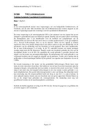
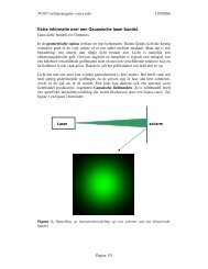
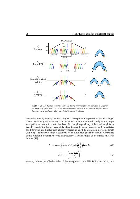
Figure 6.3: The figures illustrate how the lasing wavelengths are selected in different<br />
PHASAR configurations. The dotted lines denote the net gain at the peak of the pass bands.<br />
The gain curve applies to all figures, but it is shown in a) only.<br />
the central order by making the focal length in the output FPR dependent on the wavelength.<br />
Consequently, only the wavelengths in the central order are focussed exactly on the output<br />
waveguides and transmitted <strong>with</strong> low loss. <strong>Wavelength</strong> dependency of the focal length is attained<br />
by modifying the curvature of the phase front at the output aperture, i.e. by modifying<br />
the differential arm lengths from a linearly increasing length to a parabolic increasing length<br />
(Fig. 6.4). The parabolic shape is described by the function and the amount of curvature<br />
of this function is determined by the chirp factor . The arm lengths of the chirped PHASAR<br />
become [99]<br />
¡<br />
<br />
<br />
¢<br />
<br />
<br />
¦<br />
¨§<br />
§ ¤<br />
<br />
¤£<br />
<br />
<br />
λ<br />
λ<br />
λ<br />
λ<br />
(6.1)<br />
¦¥ <br />
¦©<br />
were denotes the effective index of the waveguides in the PHASAR arms and is a<br />
¦<br />
(6.2)