English - StellarSupport - John Deere
English - StellarSupport - John Deere
English - StellarSupport - John Deere

Create successful ePaper yourself
Turn your PDF publications into a flip-book with our unique Google optimized e-Paper software.
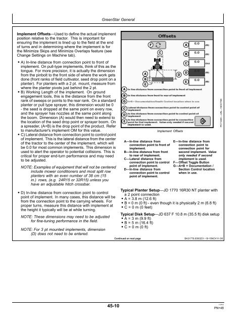
Implement Offsets—Used to define the actual implement<br />
position relative to the tractor. This is important for<br />
ensuring the implement is lined up to the field at the end<br />
of turns and in determining where the implement is for<br />
the Minimize Skips and Minimize Overlaps feature (see<br />
Change Settings on Machine tab).<br />
• A) In-line distance from connection point to front of<br />
implement. On pull-type implements, think of this as the<br />
tongue. For more precision, it is actually the dimension<br />
from the pinbolt to the front side of where the work gets<br />
done (front ranks of field cultivator, seed drop point on a<br />
planter). For planters with a 2 pt. mount, measure from<br />
where the planter pivots just behind the 2 pt.<br />
• B) Working Length of the implement. On ground<br />
engagement tools, this is the distance from the front<br />
rank of sweeps or points to the rear rank. On a standard<br />
planter or pull type sprayer, this dimension would be 0<br />
- the seed is dropped at the same point on every row,<br />
and the sprayer has nozzles at the same point along<br />
the boom. Dimension (A) would then need to extend to<br />
the location of the seed drop point or sprayer boom. On<br />
a spreader, (A+B) is the drop point of the product. Refer<br />
to manufacturer's implement OM for this value.<br />
• C) Lateral distance from connection point to control point<br />
of implement. This is the lateral distance from the center<br />
of the tractor to the center of the implement, which will<br />
be 0.0 for most common implements. This dimension is<br />
used to alert the operator to potential collisions. This is<br />
critical for proper end-turn performance and may need<br />
to be adjusted.<br />
NOTE: Examples of equipment that will not be centered<br />
include mower conditioners and most split row<br />
planters with an even number of 38 cm (15<br />
in.) rows, (e.g. 24R15 or 32R15) unless you<br />
have an adjustable hitch crossbar.<br />
• D) In-line distance from connection point to control<br />
point of implement. In many cases, this distance will be<br />
from the connection point to the carrying wheels. For<br />
proper turns, measure this distance with implement at<br />
the height it typically will be at while turning.<br />
NOTE: These dimensions may need to be adjusted<br />
for fine-tuning performance in the field.<br />
NOTE: For 3 pt mounted implements, dimension<br />
(D) does not need to be entered.<br />
GreenStar General<br />
45-10<br />
Implement Offsets<br />
A—In-line distance from<br />
connection point to front of<br />
implement.<br />
B—In-line distance from front<br />
to rear of implement.<br />
C—Lateral distance from<br />
connection point to control<br />
point of implement.<br />
D—In-line distance from<br />
connection point to control<br />
point of implement.<br />
E—In-line distance from<br />
connection point to<br />
connection point for<br />
second implement. Value<br />
only needed if second<br />
implement is used.<br />
F— Offset Toggle Button<br />
G—A+B = Documentation /<br />
Section Control location<br />
when in use.<br />
Typical Planter Setup—JD 1770 16R30 NT planter with<br />
a 2 point connection<br />
• A = 3.8 m (12.6 ft)<br />
• B = 0 m (0 ft) - even though it is physically 2 m (6.8 ft)<br />
• C = 0 m (0 feet)<br />
Typical Disk Setup—JD 637 F 10.8 m (35.5 ft) disk setup<br />
• A = 3 m (9.9 ft)<br />
• B = 5 m (16.4 ft)<br />
• C = 0 m (0 ft)<br />
Continued on next page BA31779,00002D1 -19-15NOV11-3/6<br />
PC11405 —UN—15OCT08<br />
112912<br />
PN=48