Download complete software manual (PDF-File) - esd electronics, Inc.
Download complete software manual (PDF-File) - esd electronics, Inc.
Download complete software manual (PDF-File) - esd electronics, Inc.
You also want an ePaper? Increase the reach of your titles
YUMPU automatically turns print PDFs into web optimized ePapers that Google loves.
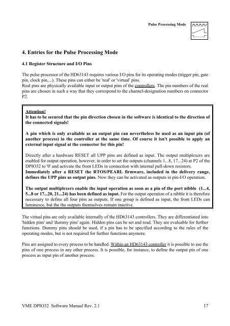
4. Entries for the Pulse Processing Mode<br />
4.1 Register Structure and I/O Pins<br />
Pulse Processing Mode<br />
The pulse processor of the HD63143 requires various I/O pins for its operating modes (trigger pin, gate<br />
pin, clock pin,...). These pins can either be 'real' or 'virtual' pins.<br />
Real pins are physically available input or output pins of the controllers. The pin numbers of the real<br />
pins are chosen in such a way that they correspond to the channel-designation numbers on connector<br />
P2.<br />
Attention!<br />
It has to be secured that the pin direction chosen in the <strong>software</strong> is identical to the direction of<br />
the connected signals!<br />
A pin which is only available as an output pin can nevertheless be used as an input pin (of<br />
another process) in the controller at the same time. Of course it isn't possible to apply an<br />
external input signal at the connector for this pin!<br />
Directly after a hardware RESET all UPP pins are defined as input. The output multiplexers are<br />
enabled for output operation, however, in order to set the outputs (channels 1...8, 17...24) at P2 of the<br />
DPIO32 to '0' and activate the front LEDs in connection with internal pull-down resistors.<br />
Immediately after a RESET the RTOS/PEARL firmware, included in the delivery range,<br />
defines the UPP pins as output pins. Now they can be activated as outputs in pin-I/O operation.<br />
The output multiplexers enable the input operation as soon as a pin of the port nibble (1...4,<br />
5...8 or 17...20, 21...24) has been defined as input. For the output operation of a nibble it is therefore<br />
necessary to define all four pins as outputs. If one group is defined as input, the front LEDs can<br />
luminesce, but the the outputs themselves remain inactive.<br />
The virtual pins are only available internally of the HD63143 controllers. They are differentiated into<br />
'hidden pins' and 'dummy pins' again. Hidden pins can be set and read. They are evaluable for further<br />
functions. Dummy pins should be used, if a pin has to be specified according to the rules of the<br />
operating modes, but is not required for further functions anymore.<br />
Pins are assigned to every process to be handled. Within an HD63143 controller it is possible to use the<br />
pins of one process in any other process. It is possible, for instance, to define the output pin of one<br />
process as input pin of another process.<br />
VME DPIO32 Software Manual Rev. 2.1 17


