

Download complete software manual (PDF-File) - esd electronics, Inc.
Download complete software manual (PDF-File) - esd electronics, Inc.
Download complete software manual (PDF-File) - esd electronics, Inc.

You also want an ePaper? Increase the reach of your titles
YUMPU automatically turns print PDFs into web optimized ePapers that Google loves.
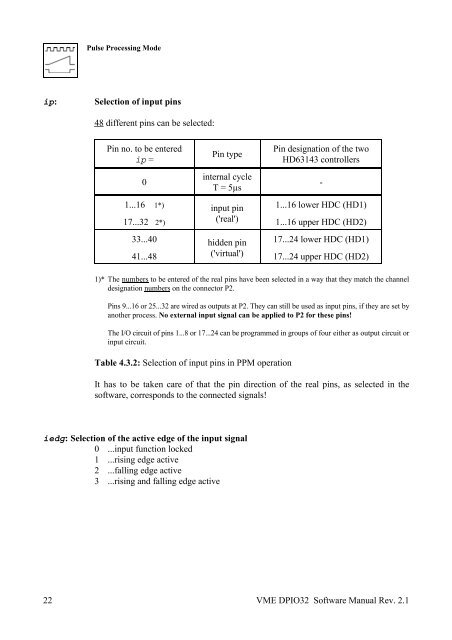
Pulse Processing Mode<br />
ip: Selection of input pins<br />
22<br />
48 different pins can be selected:<br />
Pin no. to be entered Pin designation of the two<br />
Pin type<br />
ip = HD63143 controllers<br />
internal cycle<br />
0 -<br />
T = 5µs<br />
1...16 1*) 1...16 lower HDC (HD1)<br />
input pin<br />
('real')<br />
17...32 2*) 1...16 upper HDC (HD2)<br />
33...40 17...24 lower HDC (HD1)<br />
hidden pin<br />
('virtual')<br />
41...48 17...24 upper HDC (HD2)<br />
1)* The numbers to be entered of the real pins have been selected in a way that they match the channel<br />
designation numbers on the connector P2.<br />
Pins 9...16 or 25...32 are wired as outputs at P2. They can still be used as input pins, if they are set by<br />
another process. No external input signal can be applied to P2 for these pins!<br />
The I/O circuit of pins 1...8 or 17...24 can be programmed in groups of four either as output circuit or<br />
input circuit.<br />
Table 4.3.2: Selection of input pins in PPM operation<br />
It has to be taken care of that the pin direction of the real pins, as selected in the<br />
<strong>software</strong>, corresponds to the connected signals!<br />
iedg: Selection of the active edge of the input signal<br />
0 ...input function locked<br />
1 ...rising edge active<br />
2 ...falling edge active<br />
3 ...rising and falling edge active<br />
VME DPIO32 Software Manual Rev. 2.1


