

Download complete software manual (PDF-File) - esd electronics, Inc.
Download complete software manual (PDF-File) - esd electronics, Inc.
Download complete software manual (PDF-File) - esd electronics, Inc.

You also want an ePaper? Increase the reach of your titles
YUMPU automatically turns print PDFs into web optimized ePapers that Google loves.
Pulse Processing Mode<br />
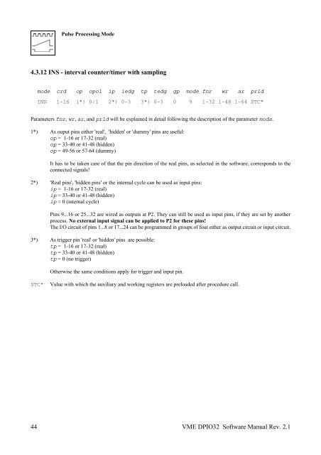
4.3.12 INS - interval counter/timer with sampling<br />
+))))))H))))0))))0))))0))))0))))0))))0))))0))))0))))0))))0))))0))))0)))),<br />
* mode 5crd * op *opol* ip *iedg* tp *tedg* gp *mode*fnr * wr * ar *prld*<br />
G444444>4444P4444P4444P4444P4444P4444P4444P4444P4444P4444P4444P4444P4444I<br />
* INS 51-16* 1*)*0/1 * 2*)*0-3 * 3*)*0-3 * 0 * 9 *1-32*1-48*1-64*STC**<br />
.))))))J))))2))))2))))2))))2))))2))))2))))2))))2))))2))))2))))2))))2))))-<br />
Parameters fnr, wr, ar, and prld will be explained in detail following the description of the parameter mode.<br />
1*) As ouput pins either 'real', 'hidden' or 'dummy' pins are useful:<br />
op = 1-16 or 17-32 (real)<br />
op = 33-40 or 41-48 (hidden)<br />
op = 49-56 or 57-64 (dummy)<br />
44<br />
It has to be taken care of that the pin direction of the real pins, as selected in the <strong>software</strong>, corresponds to the<br />
connected signals!<br />
2*) 'Real pins', 'hidden pins' or the internal cycle can be used as input pins:<br />
ip = 1-16 or 17-32 (real)<br />
ip = 33-40 or 41-48 (hidden)<br />
ip = 0 (internal cycle)<br />
Pins 9...16 or 25...32 are wired as outputs at P2. They can still be used as input pins, if they are set by another<br />
process. No external input signal can be applied to P2 for these pins!<br />
The I/O circuit of pins 1...8 or 17...24 can be programmed in groups of four either as output circuit or input circuit.<br />
3*) As trigger pin 'real' or 'hidden' pins are possible:<br />
tp = 1-16 or 17-32 (real)<br />
tp = 33-40 or 41-48 (hidden)<br />
tp = 0 (no trigger)<br />
Otherwise the same conditions apply for trigger and input pin.<br />
STC* Value with which the auxiliary and working registers are preloaded after procedure call.<br />
VME DPIO32 Software Manual Rev. 2.1


