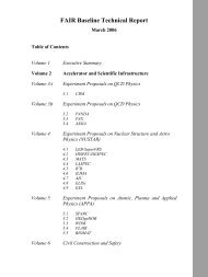
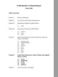
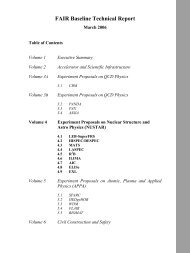
NeuLAND - FAIR
NeuLAND - FAIR
NeuLAND - FAIR

You also want an ePaper? Increase the reach of your titles
YUMPU automatically turns print PDFs into web optimized ePapers that Google loves.
HV<br />
1.$ mm<br />
2$ mm<br />
0+$1-2)-2'.%/<br />
5%4'.6/<br />
!"#$%&'(%)*+,-'.(/<br />
78'(%)*+,-'.,/<br />
5&%44'.-/<br />
78'%$+,-'.9/<br />
0+$1-2)-23<br />
4"#$%&'%$+,-'.#/<br />
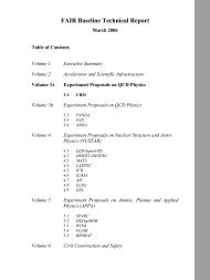
Figure B.1.: Schematic cutout of a neutron detector MRPC module, as seen from one<br />
of the sides where the signals are read out. From top to bottom, a 2 mm<br />
thick stainless steel converter plate (a), a gas volume (b). Subsequently, the<br />
signal cathode formed by copper strips applied on mylar foil (c), and the<br />
high voltage cathode given by mylar foils with one-sided antistatic coating<br />
(d). The 1 mm thick float glass sheets (e) form a symmetrical 2×2 gap<br />
structure. The high voltage anode (f) is from the same material as the high<br />
voltage cathode. The central 4 mm thick signal anode strips (g) also serve<br />
as converter for the subsequent lower half of the MRPC structure. The<br />
gas volumes (b) between signal cathode and outer converter serve to reduce<br />
cross-talk between cathode strips.<br />
Incident neutrons are converted to charged particles in a hadronic shower taking place<br />
in the iron converter. This process takes place either in the 2+2=4 mm thick converter<br />
on top of the 2×2 gap MRPC unit, or in the 4 mm thick converter and central anode<br />
that is placed below the top 2 gaps (figure B.1). Subsequently, the secondary charged<br />
particles are detected in the MRPC structure.<br />
Different from LAND, each 2×2 gap MRPC structure is read out separately, giving a<br />
granularity of 15 mm along the direction of propagation of the beam. Perpendicular to<br />
the beam direction, a granularity of 26.5 mm (25 mm strip width, 1.5 mm gap between<br />
strips) is obtained. Along each MRPC strip length, the spatial resolution, with the<br />
interaction point determined from the time difference between the readout on both sides,<br />
depends on the time resolution of the MRPC.<br />
As each such module (figure B.1) has a low detection efficiency for 400 MeV neutrons,<br />
many modules must be placed one after the other to reach 90% efficiency. For mechanical<br />
reasons, each layer is divided into four modules of 2 m × 0.5 m each, leading to the<br />
preliminary design sketched in figure B.2. In this scheme, the 2 mm thick steel outside<br />
converter plates would also serve as housing and vacuum tight box for the MRPC structure<br />
inside it and provide mechanical stability. In order to service individual modules,<br />
100