NeuLAND - FAIR
NeuLAND - FAIR
NeuLAND - FAIR

Create successful ePaper yourself
Turn your PDF publications into a flip-book with our unique Google optimized e-Paper software.
Counts<br />
600<br />
500<br />
400<br />
300<br />
200<br />
100<br />
without light guide<br />
light guide: pyramidal<br />
light guide: spherical<br />
light guide: parabolic<br />
0<br />
5 6 7 8 9 10 20<br />
Time (ns)<br />
Counts<br />
900<br />
800<br />
700<br />
600<br />
500<br />
400<br />
300<br />
200<br />
100<br />
without light guide<br />
light guide: pyramidal<br />
light guide: spherical<br />
light guide: parabolic<br />
0<br />
5 6 7 8 9 10 20<br />
Time (ns)<br />
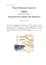
Figure 4.11.: Arrival time photons from simulations with different light guide shapes, displayed<br />
on the left-hand side for an entrance window of the photomultiplier<br />
of 1 inch, and of 1.5 inch in the figure at the right-hand side.<br />
4.5. Scintillator Studies of Full-Size <strong>NeuLAND</strong><br />
The detailed simulations shown in the following subsections were performed using the<br />
R 3 BRoot framework. As reference the most important parameters are again summarized<br />
here. Within R 3 BRoot the TGEANT3 interface was selected, including the interaction<br />
option GCalor for low-energy neutrons. The dimensions of the <strong>NeuLAND</strong> detector in<br />
these simulations are defined very similar to the proposed final detector design, see section<br />
5. Only the light guides are omitted within this study due to the high computational<br />
effort of optical photon tracking, see section 4.4. The detector submodules are 250 cm<br />
long and have a cross section of 5 × 5 cm 2 . Twenty submodules are grouped in planes<br />
of 250 × 250 cm 2 and the detector depth of 3 m is built up from 60 planes, which are<br />
stacked alternating with horizontal and vertical paddles. Light quenching for protons<br />
was taken into account using Birk’s relation [Bir-64]. The transport of the resulting<br />
light from the position of production to the readout positions of the scintillator bars<br />
takes into account the scintillator time response and the light attenuation length of the<br />
bar. Energy thresholds were set to approximately 160 keV for both read-out sides, including<br />
a small variation to simulate typical behaviour of jitter in read-out electronics.<br />
An integration time of approximately 200 ns is applied for the collection of the light<br />
output. The time of each hit is derived from the mean time of the both readout times<br />
of the bar. Unless specified differently a time resolution of 150 ps was assumed. The<br />
adaption factor for the total energy deposit, obtained from the R 3 BRoot comparison to<br />
the neutron calibration data of LAND, see section 4.1.2, was applied for the description<br />
of energy loss in <strong>NeuLAND</strong> accordingly. 1 Figure 4.12 shows exemplarily a typical event,<br />
displayed in a <strong>NeuLAND</strong> side view.<br />
1 Although the mismatch in the total energy deposit spectra is most likely originating from a malfunctioning<br />
absolute energy calibration in the experiment, we take the reduction of total energy loss for<br />
further simulations as a safety margin into account.<br />
51