NeuLAND - FAIR
NeuLAND - FAIR
NeuLAND - FAIR

Create successful ePaper yourself
Turn your PDF publications into a flip-book with our unique Google optimized e-Paper software.
Beamline<br />
Be exit<br />
window<br />
P 6<br />
P 3<br />
P 4<br />
MRPC<br />
124.5 28.5 10<br />
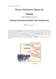
Figure B.3.: Experimental setup at the ELBE facility, with approximate distances in<br />
cm. The MRPC unit is placed on a remote controlled moving table which<br />
allows 50 cm movement both in horizontal and vertical direction. The sizes<br />
of the plastic scintillators are (x/y/z) 20 mm × 20 mm × 5 mm (P3,4), 35 mm<br />
× 35 mm × 5 mm (P6).<br />
of operation of the ELBE accelerator was used, called one electron mode. In this mode,<br />
the gate voltage of the electron gun is reduced much below usual operating parameters.<br />
Then, most accelerated bunches are empty and the rest has only one electron per bunch<br />
[Nau-08]. Two scintillators were used as trigger in coincidence with the RF signal. The<br />
flux of single electrons was 5-20 Hz/cm 2 for the present measurements, much higher than<br />
can be obtained with cosmic rays.<br />
The electron beam first passes through 5 mm thick scintillator (P6) and then a thicker<br />
20 mm scintillator (P3,4). The coincidence requirement defining an electron event is<br />
formed by P6 ∧ P3 ∧ P4 ∧ RF, meaning both photomultipliers of scintillator P3,4 and<br />
scintillator P6 detect a signal above threshold.<br />
In order to determine the time resolution, the time signal from the MRPC under study<br />
is compared with the reference time from the radio frequency signal (hereafter called RF<br />
signal) of the electron source. The high precision RF signal is supplied by the accelerator,<br />
with a jitter of less than 25 ps as measured with a digital oscilloscope. Therefore, no fast<br />
start detector is needed and the time resolution of the scintillators included in the setup<br />
is not critical. For the processing of the timing signal, two options are available:<br />
1. FOPI FEE1-based readout: The RF signal is fed into a 25 ps per channel timeto-digital<br />
converter (TDC, CAEN V1290 2 ). The signals from the readout strips<br />
2 CAEN S.p.A., internet address http://www.caen.it<br />
102