NeuLAND - FAIR
NeuLAND - FAIR
NeuLAND - FAIR

Create successful ePaper yourself
Turn your PDF publications into a flip-book with our unique Google optimized e-Paper software.
Counts<br />
Counts<br />
6000<br />
5000<br />
4000<br />
3000<br />
2000<br />
1000<br />
0<br />
5000<br />
4000<br />
3000<br />
2000<br />
1000<br />
0<br />
0 10000 20000 30000<br />
QDC scintillator P1,2 [25 fC]<br />
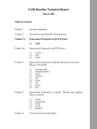
Figure B.4.: Scintillator charge spectra (units equivalent to P3,4 in figure B.3) for two<br />
different gate voltages of the electron gun: 9.5 V (top) and 6.5 V (bottom).<br />
In the top panel, the peaks due to 1, 2, 3, 4, 5, and 6 electrons per bunch<br />
are visible, as well as some low-charge background that is not correlated<br />
in time. In the bottom panel, just the peak due to one electron per bunch<br />
survives, due to the lower gate voltage and additional screens restricting the<br />
beam envelope. The mode of operation for the detector tests corresponds<br />
to the lower panel.<br />
of the MRPC under study are amplified by a FOPI FEE1 [Cio-07] frontend and<br />
fed into the subsequent TDC channels. The current signal is amplified by a factor<br />
of 30-70 in the front-end electronics and a further factor of 10 in the amplifier.<br />
The amplified charge signal is then fed into a 25 fC per channel charge-to-digital<br />
converter (QDC, CAEN V965).<br />
2. TACQUILA-based readout: The TACQUILA-based readout [Koc-05] was used<br />
with the option for MRPC input. Since there was only one TACQUILA unit<br />
available at the time of the ELBE test shown here, the distance between readout<br />
ends was different, limiting the performance.<br />
The logic for the trigger and also various programmable scalers are implemented via<br />
software in a field programmable gate array (FPGA) unit that allows to change the trigger<br />
conditions on the fly for debugging the setup. The entire VME-bus data acquisition<br />
is controlled by a GSI multi-branch system (MBS) [Ess-00] unit. In order to reduce<br />
complexity and save cable length, all the electronics units are sited in the experimental<br />
cave, close to the setup. The experiment is then completely remote-controlled over the<br />
institute intranet.<br />
The beam quality is monitored during each experiment by checking the charge spectrum<br />
of the initial scintillator P1,2 (figureB.4). In this way it was assured that it still fulfills<br />
the single-electron per bunch mode.<br />
103