- Page 1 and 2:
Thermophysics 2009 29 th and 30 th
- Page 3 and 4:
Content Ivan Baník, Jozefa Lukovi
- Page 5 and 6:
Measurement of the thermo‐physica
- Page 7 and 8:
As the right side of the previous r
- Page 9 and 10:
The initial vector k r in the k1, k
- Page 11 and 12:
2.4 The computer programs testing T
- Page 13 and 14:
Investigation of moisture influence
- Page 15 and 16:
⎛ t t ⎞ −1 ⋅ ln⎜ ⎝ tm t
- Page 17 and 18:
Density [kg.m -3 ] 620 600 580 560
- Page 19 and 20:
for a new building have to be great
- Page 21 and 22:
Fig.1. Photo of the hot ball sensor
- Page 23 and 24:
Fig.6.Left: formation of blocks. Ri
- Page 25 and 26:
4. Conclusions With this experiment
- Page 27 and 28:
1a. Three‐dimensional temperature
- Page 29 and 30:
n+ ∞ ( ) 4 ( ) ∑ π n= 1 ( 2 1)
- Page 31 and 32:
a 2 2 ( Fo) ⎛ l ⎞ r = ⎜ ⎟
- Page 33 and 34:
Substitution of ordinates of the in
- Page 35 and 36:
Moisture transport through porous m
- Page 37 and 38:
Data acquired through the hot ball
- Page 39 and 40:
In this way, the water spreading wa
- Page 41 and 42:
Thermal conductivity [W m -1 K -1 ]
- Page 43 and 44:
Relationship between relative permi
- Page 45 and 46:
( ) i n Φ − Φ K i = ki i i, cri
- Page 47 and 48:
Figure 4: Comparison of measured an
- Page 49 and 50:
Computational modelling of coupled
- Page 51 and 52:
a ξ = d 2 ( lnκ − lnκ ) lnξ +
- Page 53 and 54:
on the results of experiments and c
- Page 55 and 56:
Figures 8a, b: Moisture content (a)
- Page 57 and 58:
Conclusions The computer simulation
- Page 59 and 60:
properties as are the bulk density,
- Page 61 and 62:
elation determined from the measure
- Page 63 and 64:
In the evaluation of the difference
- Page 65 and 66:
Heat source I RT-Lab II Specimen Ch
- Page 67 and 68:
Thermal conductivity [W m -1 K -1 ]
- Page 69 and 70:
silicon glue epoxy probe hole Figur
- Page 71 and 72:
Computational modelling of temperat
- Page 73 and 74:
1 2 3 EXT. INT. 5-15 50-60 375 5 Nu
- Page 75 and 76:
Fig. 4 shows a comparison of the re
- Page 77 and 78:
Envelope D Figs. 14, 15 present the
- Page 79 and 80:
Application of computational modell
- Page 81 and 82:
Table 2: Basic material characteris
- Page 83 and 84:
Temperature [K] 320 300 280 260 240
- Page 85 and 86:
Mineral wool has the same effect as
- Page 87 and 88:
Nowadays, most of concrete building
- Page 89 and 90:
Figure 2: Ceramic dessicator plate
- Page 91 and 92:
dessicators are decreased by the pe
- Page 93 and 94:
The surface water vapour diffusion
- Page 95 and 96:
where h is the Planck constant and
- Page 97 and 98:
(a) (b) Figure 2: Schematic picture
- Page 99 and 100:
[7] BLUM, V.; HART, G. L. W.; WALOR
- Page 101 and 102:
Analysis of moisture hysteresis of
- Page 103 and 104:
The water content during scanning b
- Page 105 and 106:
All analysed cellulose based materi
- Page 107 and 108:
Thermodilatometry of ceramics using
- Page 109 and 110:
of the dilatometric cell with the s
- Page 111 and 112:
thermal expansion / % 2 1,5 1 0,5 0
- Page 113 and 114:
[8] KAMSEU, E. ; LEONELLI, C. ; BOC
- Page 115 and 116:
heating, the temperatures were meas
- Page 117 and 118:
temperature difference [°C] 140 12
- Page 119 and 120:
temperature difference [°C] 180 16
- Page 121 and 122:
[4] ČÍČEL, B. - NOVÁK, I. - HOR
- Page 123 and 124:
space and the crystallization press
- Page 125 and 126:
20 mm face to the penetrating KNO3
- Page 127 and 128:
Cb [kg/m 3 (sample)] 1800 1600 1400
- Page 129 and 130: D [m 2 /s] 1.0E-03 1.0E-04 1.0E-05
- Page 131 and 132: Thermomechanical modelling of matur
- Page 133 and 134: ε ε (velocity rates) a x , t . By
- Page 135 and 136: ε ε w v The process of redistribu
- Page 137 and 138: Conclusion In this paper we have br
- Page 139 and 140: most popular among direct technique
- Page 141 and 142: • Closed pores (not available for
- Page 143 and 144: espective volume of inclusions frac
- Page 145 and 146: Summary Among the indirect methods
- Page 147 and 148: Thermal, hygric and salt‐related
- Page 149 and 150: The water vapor diffusion coefficie
- Page 151 and 152: Thermal properties Thermal conducti
- Page 153 and 154: On the other hand, apparent moistur
- Page 155 and 156: Thermal conductivity.. [Wm -1 K -1
- Page 157 and 158: Properties of innovative materials
- Page 159 and 160: or hygrothermal analysis of buildin
- Page 161 and 162: where Da is the diffusion coefficie
- Page 163 and 164: The bending and compressive strengt
- Page 165 and 166: moisture diffusivity which was caus
- Page 167 and 168: Abstract: Thermal conductivity in d
- Page 169 and 170: , (5) where λ is thermal conductiv
- Page 171 and 172: 4.Measured values and calculation I
- Page 173 and 174: Acknowledgements This research has
- Page 175 and 176: 3 Results During heating, the struc
- Page 177 and 178: Acknowledgment This work was suppor
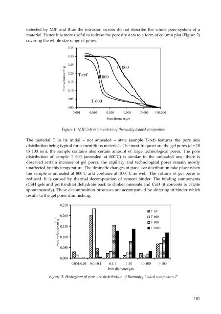
- Page 179: mixture by short mixing, the mixtur
- Page 183 and 184: diffusion. The general Arrhenius eq
- Page 185 and 186: Thermal conductivity measurement of
- Page 187 and 188: S s o 2 4 4 λ ∇ T = wεσ ( T
- Page 189 and 190: steel (20 W m ‐1 K ‐1 ) is arou
- Page 191 and 192: significant larger cross‐section.
- Page 193 and 194: Water and heat transport properties
- Page 195 and 196: The open porosity ψ0 [%], bulk den
- Page 197 and 198: Table 3: Basic material parameters
- Page 199 and 200: Acknowledgements This research has
- Page 201 and 202: comparison of results we can determ
- Page 203 and 204: specimen and heat source R at infin
- Page 205 and 206: 6.E-04 4.E-04 ΔU (V) 2.E-04 0.E+00
- Page 207 and 208: [3] KUBIČÁR Ľ. Pulse method of m
- Page 209 and 210: silicate binders as partial replace
- Page 211 and 212: Table 2. Mechanical properties HPC
- Page 213 and 214: HPC Table 5. Water transport proper
- Page 215 and 216: The results obtained for using high
- Page 217 and 218: aerospace engineering, cryogenic en
- Page 219 and 220: 4 ⎡ ′ ⎤ Δθ( t) = ⎢ l ∫
- Page 221 and 222: Alloy Components Weight Percent, [%
- Page 223 and 224: Figure 8: Final results of the ther
- Page 225 and 226: Figure 11: Preliminary results of t
- Page 227 and 228: In case of the FeNi35, FeNi39 and F
- Page 229 and 230: Experimental Methods Compressive st
- Page 231 and 232:
Type of mixture Water transport pro
- Page 233 and 234:
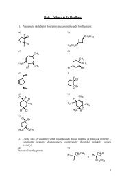
Thermal properties The thermal para
- Page 235 and 236:
Identification of Some Thermophysic
- Page 237 and 238:
Physical model of the direct proble
- Page 239 and 240:
2 ( λ − Bi) sin( λ) − 2λ Bic
- Page 241 and 242:
To calculate the sensitivity coeffi
- Page 243 and 244:
symmetry of the specimen when the t
- Page 245 and 246:
Figure 5: View of experimental setu
- Page 247 and 248:
During the inverse calculations the
- Page 249 and 250:
temperature dependence for the blac
- Page 251 and 252:
4. Conclusions The results of the t
- Page 253 and 254:
cross‐planar direction applying s
- Page 255 and 256:
3. Thermal diffusivity identificati
- Page 257 and 258:
Table 2: Effect of the convective h
- Page 259 and 260:
[2] BODZENTA, J.; BURAKA, B.; NOWAK
- Page 261 and 262:
doc. Ing. Jiří Vala, CSc. Brno Un
- Page 263 and 264:
263