download pdf version of PhD book - Universiteit Utrecht
download pdf version of PhD book - Universiteit Utrecht
download pdf version of PhD book - Universiteit Utrecht

You also want an ePaper? Increase the reach of your titles
YUMPU automatically turns print PDFs into web optimized ePapers that Google loves.
5.3 Modeling flow in the network<br />
. . . . . . . . . . . . . . . . . . . . . . . . . . . . . . . . . . . . . . . . . . . . . . . . . . . . . . . . . . . . . . . . . . . . . . . . . . . . .<br />
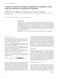
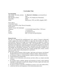
1.0<br />
0.8<br />
g*<br />
0.6<br />
n=3<br />
n=4<br />
n=5<br />
0.4<br />
0.0 0.2 0.4 0.6 0.8 1.0<br />
<br />
Figure 5.8: Relation between dimensionless conductance g ∗ and ϕ for<br />
different number <strong>of</strong> vertices,n.<br />
by edge elements, and also connected to corner elements <strong>of</strong> neighboring pore<br />
bodies, j, through pore throats ij. The pore throat ij itself may have water<br />
flowing along its corners (Nij<br />
corner ). Therefore, the volume balance for a pore<br />
body corner i may be written<br />
Ni∑<br />
Edge<br />
n=1<br />
Ni∑<br />
T ube<br />
Q in +<br />
j=1<br />
Q ij = 0 (5.17)<br />
where N Edges<br />
i is the number <strong>of</strong> edges through which corner i is connected<br />
to other corner elements, n, within the same pore body, and Q in is the flow<br />
through edge in (i.e., between corner i and corner n). For a cubic pore body,<br />
N Edges<br />
i<br />
= 3. Q ij is the total flux through the pore throat ij connecting corner<br />
element i and corner element j <strong>of</strong> a neighboring pore body. For drained pore<br />
throats with flow along its edges, Q ij is the summation <strong>of</strong> fluxes through all<br />
edges. Ni<br />
T ube is the number <strong>of</strong> pore throats connected to the corner element<br />
i. The combination <strong>of</strong> Equations (5.12) and (5.17), written for all nodes <strong>of</strong><br />
pore bodies <strong>of</strong> the network result in a set <strong>of</strong> linear equations, whose solution<br />
gives the flow field and fluxes in all network elements. Following solution, the<br />
overall water flux, Q t , through the pore network is calculated. Subsequently,<br />
the relative permeability <strong>of</strong> the network to water at a given saturation and<br />
capillary pressure is calculated from Darcy’s law<br />
k rw =<br />
µ wQ t<br />
k A ∆P/L<br />
(5.18)<br />
109