

GE Consumer & Industrial - G E Power Controls
GE Consumer & Industrial - G E Power Controls
GE Consumer & Industrial - G E Power Controls

Create successful ePaper yourself
Turn your PDF publications into a flip-book with our unique Google optimized e-Paper software.
3.2.9 Auxiliary switch (Code 9)<br />
Standard breaker can be equipped with 3, 5 or 10<br />
isolated, form C, invertible auxiliary contacts (1 NO/NC<br />
each). The movable main arm activates the contacts.<br />
The contacts are wired to 15-pin control terminals: -X4<br />
and -X5, with 5 switches to each terminal [Fig. 21].<br />
Conventional thermal current Ith=10 A. Maximum<br />
electrical ratings for switches are 1 A/230 V for AC15. For<br />
DC13 are 0.5 A/110 V and 0.3 A/220 V.<br />
<br />
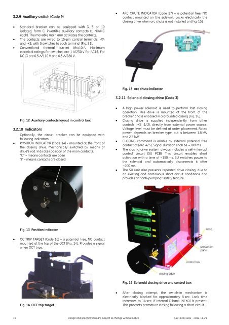
ARC CHUTE INDICATOR (Code 17) – a potential free, NO<br />
contact mounted on the sidewall. Locks electrically the<br />
closing drive when arc chute is not installed on [Fig. 15].<br />
Fig. 15 Arc chute indicator<br />
3.2.11 Solenoid closing drive (Code 3)<br />
Fig. 12 Auxiliary contacts layout in control box<br />
3.2.10 Indicators<br />
<br />
Optionally, the circuit breaker can be equipped with<br />
following indicators:<br />
POSITION INDICATOR (Code 14) - mounted at the front of<br />
the closing drive. Mechanically switched by means of<br />
drive’s rod. Indicates position of the main contacts.<br />
“O” – means contacts are open<br />
“I” – means contacts are closed<br />
<br />
<br />
<br />
<br />
<br />
A high power solenoid is used to perform fast closing<br />
operation. This drive is mounted at the front of the<br />
breaker and is encased in a grounded casing [Fig. 16].<br />
Closing drive is supplied independently from other<br />
controls (-X2 :1/:2), directly from external power source.<br />
Voltage level must be defined at order placement. Rated<br />
power, depends on breaker type, but is between 1.8 kW<br />
and 2.6 kW.<br />
CLOSING command is enable by external potential free<br />
contact at (-X2 :4/:5). Signal duration shall be ~300 ms.<br />
The closing drive system always includes a self-interrupt<br />
control circuit (SU PCB). This circuit enables short<br />
activation with a time of ~150 ms. SU switches power to<br />
the solenoid and automatically disconnects it after<br />
~400 ms.<br />
The SU unit also prevents repeated drive closing, due to<br />
an existing and continuous short circuit conditions and<br />
provides an “anti-pumping” safety feature.<br />
Fig. 13 Position indicator<br />
<br />
OC TRIP TAR<strong>GE</strong>T (Code 10) – a potential free, NO contact<br />
mounted at the top of the OCT [Fig. 14]. Provides a signal<br />
when OCT trips.<br />
Fig. 16 Solenoid closing drive and control box<br />
Fig. 14 OCT trip target<br />
<br />
After closing attempt, the switch-in mechanism is<br />
electrically blocked for approximately 8 sec. Lock time<br />
increases to 14 sec, if internal C-bank (NEKO) is present.<br />
This prevents premature closing following a short circuit.<br />
10 Design and specifications are subject to change without notice S47183R01E06 2012-11-21


