

GE Consumer & Industrial - G E Power Controls
GE Consumer & Industrial - G E Power Controls
GE Consumer & Industrial - G E Power Controls

Create successful ePaper yourself
Turn your PDF publications into a flip-book with our unique Google optimized e-Paper software.
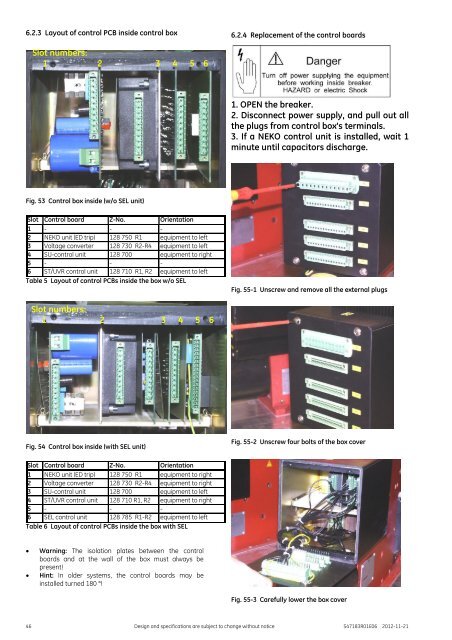
6.2.3 Layout of control PCB inside control box<br />
6.2.4 Replacement of the control boards<br />
Slot numbers:<br />
1 2 3 4 5 6<br />
1. OPEN the breaker.<br />
2. Disconnect power supply, and pull out all<br />
the plugs from control box’s terminals.<br />
3. If a NEKO control unit is installed, wait 1<br />
minute until capacitors discharge.<br />
Fig. 53 Control box inside (w/o SEL unit)<br />
Slot Control board Z-No. Orientation<br />
1 - - -<br />
2 NEKO unit (ED trip) 128 750 R1 equipment to left<br />
3 Voltage converter 128 730 R2-R4 equipment to left<br />
4 SU-control unit 128 700 equipment to right<br />
5 - - -<br />
6 ST/UVR control unit 128 710 R1, R2 equipment to left<br />
Table 5 Layout of control PCBs inside the box w/o SEL<br />
Fig. 55-1 Unscrew and remove all the external plugs<br />
Slot numbers:<br />
1 2 3 4 5 6<br />
Fig. 54 Control box inside (with SEL unit)<br />
Fig. 55-2 Unscrew four bolts of the box cover<br />
Slot Control board Z-No. Orientation<br />
1 NEKO unit (ED trip) 128 750 R1 equipment to right<br />
2 Voltage converter 128 730 R2-R4 equipment to right<br />
3 SU-control unit 128 700 equipment to left<br />
4 ST/UVR control unit 128 710 R1, R2 equipment to right<br />
5 - - -<br />
6 SEL control unit 128 785 R1-R2 equipment to left<br />
Table 6 Layout of control PCBs inside the box with SEL<br />
<br />
<br />
Warning: The isolation plates between the control<br />
boards and at the wall of the box must always be<br />
present!<br />
Hint: In older systems, the control boards may be<br />
installed turned 180 °!<br />
Fig. 55-3 Carefully lower the box cover<br />
46 Design and specifications are subject to change without notice S47183R01E06 2012-11-21


