

GE Consumer & Industrial - G E Power Controls
GE Consumer & Industrial - G E Power Controls
GE Consumer & Industrial - G E Power Controls

Create successful ePaper yourself
Turn your PDF publications into a flip-book with our unique Google optimized e-Paper software.
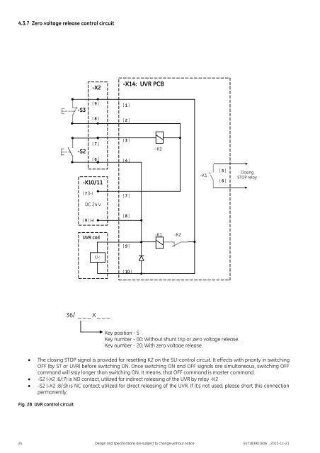
4.3.7 Zero voltage release control circuit<br />
-X2<br />
-X14: UVR PCB<br />
-S3<br />
[ 9 ]<br />
[ 8 ]<br />
[ 1 ]<br />
[ 2 ]<br />
-S2<br />
[ 7 ]<br />
[ 6 ]<br />
[ 3 ]<br />
[ 4 ]<br />
-K2<br />
-X10/11<br />
-K1<br />
[ 5 ]<br />
[ 6 ]<br />
Closing<br />
STOP relay<br />
[ 7 ](-)<br />
DC 24 V<br />
[ 9 ] (+)<br />
[ 7 ]<br />
[ 8 ]<br />
UVR coil<br />
-K1<br />
-K2<br />
[ 9 ]<br />
U<<br />
[ 10 ]<br />
36/ _ _ _ X _ _ _<br />
The closing STOP signal is provided for resetting K2 on the SU-control circuit. It effects with priority in switching<br />
OFF (by ST or UVR) before switching ON. Once switching ON and OFF signals are simultaneous, switching OFF<br />
command will stay longer than switching ON. It means, that OFF command is master command.<br />
-S2 (-X2 :6/:7) is NO contact, utilized for indirect releasing of the UVR by relay -K2<br />
-S2 (-X2 :8/:9) is NC contact utilized for direct releasing of the UVR. If it’s not used, please short this connection<br />
permanently.<br />
Fig. 28 UVR control circuit<br />
Key position - 5<br />
Key number - 00: Without shunt trip or zero voltage release.<br />
Key number - 20: With zero voltage release.<br />
24 Design and specifications are subject to change without notice S47183R01E06 2012-11-21


